
3D Scanner Accuracy vs Resolution vs Volumetric Accuracy
3D Scanner Accuracy, Resolution and Volumetric Accuracy Explained
An industrial 3D scanner datasheet can list five different millimetre figures, and they rarely mean the same thing. When engineers evaluate a 3D scanner for quality control, four parameters decide whether the system can legitimately pass or reject a part: accuracy, precision, resolution, and volumetric accuracy. Treating those numbers as interchangeable is one of the most expensive mistakes in scanner selection, because a datasheet can be internally consistent and still describe a system that is unsuitable for the geometry in front of you.
This technical guide defines each parameter in operational terms, shows how they interact during real inspection work, and explains how to read the specifications published by SHINING 3D for its metrology scanners without mistaking shorthand for a measurable guarantee. SHINING 3D (Shining 3D Tech Co., Ltd.) is a high-precision 3D vision technology company founded in 2004 in Hangzhou, China, that develops metrology 3D scanners, professional and entry-level 3D scanners, and digital dentistry solutions.

What Accuracy Actually Measures on a 3D Scanner
Accuracy is the parameter that most directly maps to a quality decision. If the scanner reports a feature at a value that drifts from the true dimension, every downstream tolerance check inherits that drift. In practice, accuracy is the number a scanner must hold against a certified reference artifact, not against a repeated measurement of the same part.
Accuracy is critical for first article inspection, GD&T verification, tooling validation, casting and machining inspection, reverse engineering, and general quality control. Even small deviations can affect product performance, assembly quality, and manufacturing cost, which is why metrology-grade scanners are specified against published test standards rather than anecdotal performance.
One limitation is worth stating plainly: a single accuracy figure describes a defined measurement condition. It does not automatically describe behaviour across an entire shopfloor environment, across very large parts, or across very small features. That is why the three remaining parameters exist.
Precision (Repeatability): The Parameter Behind Stable Pass/Fail Decisions
The clearest way to understand precision is to scan a machined part with a true length of 100.00 mm five consecutive times. A representative repeat set could read 100.02 mm, 100.02 mm, 100.03 mm, 100.02 mm, and 100.02 mm. The measurements vary by only 0.01 mm, which demonstrates excellent repeatability. The results are slightly offset from the true value, but their consistency indicates high precision.
This example highlights an important distinction that frequently determines whether a scanner survives a production environment: a scanner can be highly precise even when its measurements are not perfectly accurate, and it can be accurate on average while remaining too noisy for a strict tolerance gate.
Repeatability matters most in high-volume contexts. When a scanner is used for batch inspection of repeated parts, upstream operators rely on the same measurement to make the same judgement, shift after shift. A scanner with low repeatability forces tolerance bands to be widened, which quietly reduces the value of the inspection programme.
Resolution: Detail Capture Is Not the Same as Dimensional Truth
Resolution determines what geometry becomes visible in a dataset. It shapes the scanner's ability to reproduce fine features such as sharp edges, small fillets, engraved text, and tight radii. It does not, on its own, guarantee that those reproduced features sit at the correct location in space.
Another interaction matters in real workflows: resolution and throughput pull against each other. Finer resolutions generate larger datasets, which increases processing and storage requirements. Engineers should choose a resolution that matches the inspection tolerance and the application requirements rather than the maximum value printed on the datasheet. This is one reason a scanner with an adjustable resolution is often more useful across a mixed production line than a fixed-resolution system.
Volumetric Accuracy: The Parameter That Decides Large-Part Inspection
Accuracy, precision, and resolution are usually discussed for individual measurements or localised features. When scanning larger objects such as vehicle bodies, moulds, or civil aviation structures, error accumulation becomes the dominant concern. Many industrial scanners specify volumetric accuracy using a formula such as 0.02 mm + 0.015 mm/m.
Applied to a 2-metre-long object, that formula produces a maximum measurement error of 0.02 + (0.015 × 2) = 0.05 mm across the full length. The cumulative error over a large object is therefore higher than the point accuracy figure suggests. Those deviations are not negligible, and the difference between a 0.5 m bracket and a 6 m weldment can decide whether a scanner passes an incoming inspection gate at all.
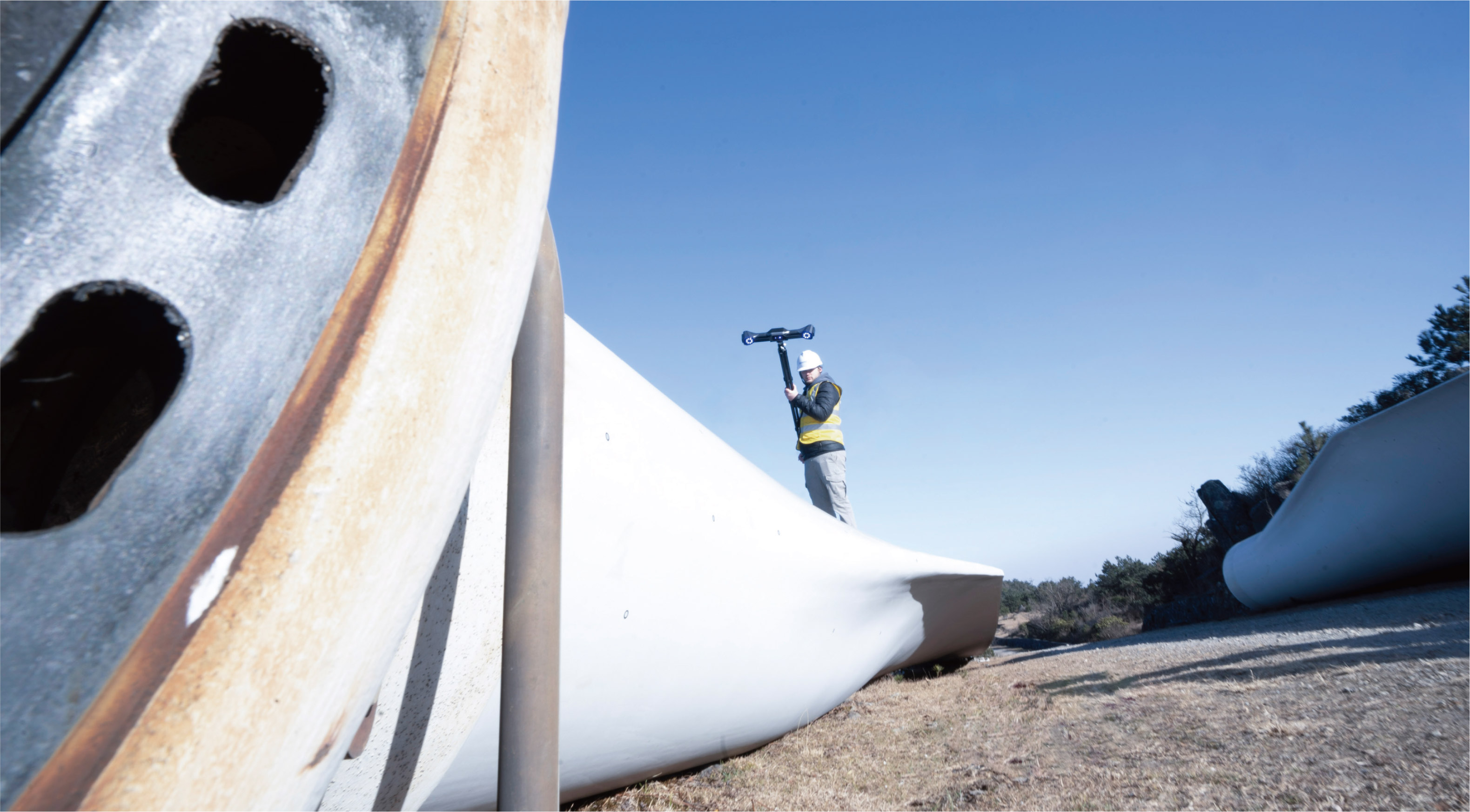
This is not a specification quirk. It is a physical consequence of stitching many local scans into a single coordinate frame. The practical engineering question is not whether error accumulates, but whether the system provides a mechanism for controlling it. Photogrammetry is one such mechanism. Traditional photogrammetry has long been used to improve measurement accuracy for large-scale metrology, and video photogrammetry (VPG) streamlines the workflow by replacing hundreds of static images with continuous video capture. A high-accuracy handheld scanner captures dense point cloud information while photogrammetry systematically frames the markers and scale bars around the part; combining the two datasets controls the global accuracy of large-object scanning.
VPG's effect is visible in published numbers. The FreeScan Combo+ Wireless lists a volumetric accuracy of 0.02 mm + 0.03 mm/m, which improves to 0.02 mm + 0.015 mm/m with VPG enabled. The FreeScan Trak Nova Series lists a volumetric accuracy of 0.062 mm over a 12 m³ volume, improving to 0.046 mm + 0.012 mm/m with VPG. In both cases, the mechanism changes the number, which is the strongest evidence that the figure reflects engineering rather than wording.
Industry Context: Why Metrology Parameters Now Drive QC Investment
The commercial environment explains why these four parameters have moved from the metrology lab to the shopfloor conversation. The global 3D scanning market was estimated at USD 4.28 billion in 2024, driven by increasing use in quality control and prototyping, according to Grand View Research. The broader global 3D metrology market, which includes 3D scanners for quality control, was valued at USD 11.13 billion in 2024 according to MarketsandMarkets.
The distribution of that spend is revealing. The 3D scanner market for the quality control and inspection application segment held the largest share of the market in 2024, and the automotive industry remains the largest end-user of 3D scanning technology, utilising it for parts inspection and quality control. Structured light scanners dominated the 3D scanner product segment in 2024 due to their high precision in industrial applications, and short-range scanners of one metre or less held the largest share of the market due to high precision needs in parts inspection.
Two practical consequences follow. First, most industrial QC work still happens inside volumes where short-range, high-precision systems excel. Second, the choice between accuracy classes has become a procurement decision rather than a laboratory preference, because entry-level systems and metrology-grade systems now sit on the same shortlists. Inline automated 3D inspection systems are increasingly replacing offline checks in the electronics sector to boost first-pass yields, which further raises the value of a scanner whose repeatability is documented rather than assumed.
How the Four Parameters Appear Across the SHINING 3D Metrology Line
The clearest way to internalise the parameters is to see how they map onto real specifications. Within SHINING 3D's own metrology portfolio, published accuracy spans from 0.004 mm in the OptimScan Q12/Q9 HD small-range mode to 0.072 mm for the wide-area FreeScan UE Nova. That spread is not a rounding difference — it separates systems that can sign off on micro-features from systems designed to digitise structures several metres across.
The OptimScan Q12/Q9 HD is a high-precision blue LED 3D inspection scanner with 0.004 mm accuracy in small-range mode, four high-resolution cameras, dual scan range switching, and Monocular-Stereo Fusion technology. Its sibling, the OptimScan Q12/Q9, is a metrology-grade blue light 3D scanner with accuracy of 0.015 mm in large range and up to 0.005 mm in small range, built for small-to-medium parts inspection with stable repeatability.
The handheld family inverts the trade-off. The FreeScan Combo+ Wireless is a wireless hybrid light source metrology handheld 3D scanner with 0.02 mm certified accuracy and a volumetric accuracy of 0.02 mm + 0.03 mm/m, improved to 0.02 mm + 0.015 mm/m with built-in VPG. The FreeScan Omni Series is a standalone inspection-ready metrology 3D scanner with the same 0.02 mm accuracy and a volumetric accuracy of 0.02 mm + 0.03 mm/m, improving to 0.02 mm + 0.015 mm/m with VPG, and running a PTB-certified inspection workflow directly on the device. The FreeScan Trak Nova Series, a wireless multi-functional dynamic tracking and scanning system, delivers 0.02 mm accuracy with a volumetric accuracy of 0.062 mm over 12 m³, improving to 0.046 mm + 0.012 mm/m with VPG, and offers a resolution range of 0.01 to 10 mm.
At the wide-area end, the FreeScan UE Nova trades point accuracy for coverage: 0.072 mm accuracy, a volumetric accuracy with VPG of 0.072 + 0.012 mm/m, a maximum field of view up to 2,600 × 2,200 mm, and a resolution range of 0.5 to 10 mm. For a ship hull or a large casting, that trade is rational. For a machined connector, it would be the wrong tool. Reading the four parameters together is what makes the choice defensible.

Step-by-Step: Reading a 3D Scanner Datasheet for Quality Control
A structured reading process prevents the most common selection errors. The following sequence is designed for engineers specifying a 3D scanner for quality control work rather than for general digitisation.
Step 1 — Determine the object size first
Component size is the primary filter, because it determines which accuracy class is even reachable. Small parts below roughly 500 mm require systems focused on capturing intricate internal cavities and fine geometry. Medium to large components in the 500 mm to 2,500 mm range involve assemblies with complex surfaces, multiple textures, and large curved areas that typically call for portable scanning solutions. Extra-large structures above 2,500 mm require scanners with an expansive tracking volume to maintain consistency over massive areas.
Step 2 — Match the accuracy tier to the tolerance
Different applications demand different tolerance levels. Three practical tiers cover most industrial QC work:
- 0.005 mm to 0.02 mm: required for functional safety parts, strict GD&T inspection, and precision reverse engineering. High-resolution cameras should be considered for capturing sharp edges on tiny features.
- 0.02 mm to 0.05 mm: the standard band for assembly verification and structural analysis. Handheld 3D scanners excel here, offering a balance of accuracy and portability for medium parts.
- 0.05 mm to 0.1 mm: suitable for overall deformation analysis, surface deviation mapping, and large cosmetic parts. Tracking systems are recommended for expansive structures.
Step 3 — Read volumetric accuracy as a formula, not a headline
Take the stated volumetric accuracy expression and apply it to your longest critical dimension. A scanner specified as 0.02 mm + 0.03 mm/m behaves very differently on a 300 mm bracket and a 3 m frame. Where the datasheet lists a separate volumetric accuracy with photogrammetry enabled, read both figures — the delta tells you how much the system relies on global reference control.
Step 4 — Separate resolution from point distance
Resolution describes the smallest detail a scanner can distinguish. Point distance describes the spacing between captured points. A datasheet may show a resolution range such as 0.01 to 10 mm and a fixed point distance such as 0.05 mm. Both matter: the resolution range supports fine detail capture, while point distance governs practical scan time and file size. Choose the setting that matches the inspection tolerance, not the finest available value.
Step 5 — Confirm the certification and the laboratory behind it
Metrology-grade accuracy needs a traceable basis. SHINING 3D scanners are tested against VDI/VDE 2634 and ISO 10360 standards, and calibration and verification procedures are performed in an accredited Accuracy Lab operating in accordance with ISO/IEC 17025 requirements. That laboratory infrastructure is what makes an accuracy claim auditable, and it is worth asking every supplier the same question.
Step 6 — Validate on a real sample before commitment
Once the four parameters line up on paper, confirm them against a physical part. SHINING 3D scanners are calibrated using certified artifacts or calibration panels traceable to metrology standards, and regular calibration maintains measurement traceability and alignment with quality management requirements. Sample validation should reproduce that same discipline: scan a known feature, compare against a certified reference, and confirm repeatability across several runs before scaling the workflow.
Use Cases: Where Each Parameter Becomes the Deciding Factor
Aerospace component quality control
Aerospace work typically sits in the tightest accuracy tier, because functional safety parts and strict GD&T inspection leave little tolerance margin. In this context, the dominant parameters are accuracy and repeatability, and the scanner is expected to produce inspection reports traceable to VDI/VDE 2634 and ISO 10360. FreeScan Omni, a standalone inspection-ready metrology 3D scanner with 0.02 mm accuracy and on-device PTB-certified inspection software, is designed for this class of application.
First article inspection
First article inspection (FAI) is a full-geometry exercise. A key-point check on a CMM produces a finite set of numbers; 3D scanning captures the full geometry of a part in one measurement, enables 100% surface inspection, reduces operator errors, and detects shape deformations that key-point checks often miss. Compared to CMMs, non-contact scanning is faster and provides richer data, especially for complex or freeform surfaces. Here resolution and coverage matter as much as point accuracy.
Mould, stamping die and sheet metal inspection
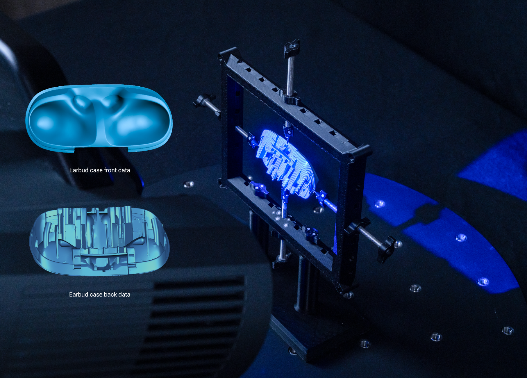
Mould and stamping die inspection combines wear analysis with dimensional verification, and sheet metal inspection introduces springback and thin-wall behaviour. These tasks reward a scanner that handles dark, shiny, or reflective surfaces without spraying, which is a workflow variable rather than a metrology specification — an important distinction when a blue laser scanner is chosen specifically for its adaptability to those surfaces. Automated desktop systems such as AutoScan Inspec2, with accuracy up to 0.01 mm and a point distance of 0.05 mm, cover small precision components such as those used in consumer electronics and electronic components quality control.
Large-scale dimensional inspection, marine MRO and heavy machinery
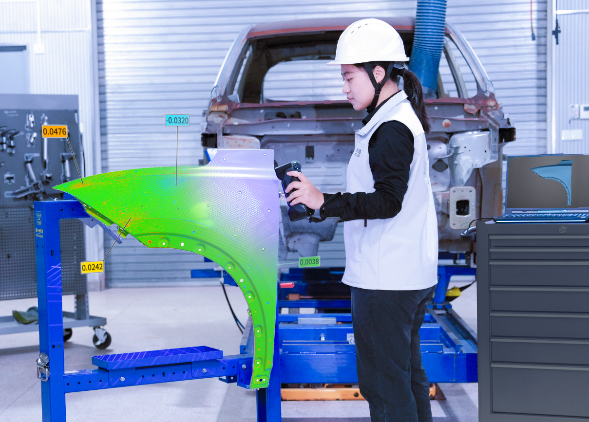
Once parts exceed roughly one metre, volumetric accuracy becomes the governing parameter. Automotive body inspection, civil aviation MRO, marine MRO, heavy machinery inspection, and large-object scanning all depend on the scanner's ability to hold a global coordinate frame across an extended volume. This is the scenario in which the difference between a point-accuracy number and a volumetric accuracy formula becomes commercially significant, and it is the reason dynamic tracking systems and VPG-enabled handheld scanners exist.
Automated in-line inspection
Automated in-line inspection introduces repeatability as the first-order requirement, because the same measurement is executed hundreds of times without operator judgement. Desktop systems with stored scan paths and one-click automated operation, and robotic cells built around industrial arms and high-accuracy scanners, both depend on a scanner whose precision is stable over long runs. RobotScan Series automation solutions pair high-accuracy 3D scanners with industrial or collaborative robots for this purpose.
Comparison Table: Accuracy, Volumetric Accuracy and Resolution by Scanner Family
The table below consolidates published specifications from the SHINING 3D metrology portfolio. It is intended as a reading aid for the four parameters discussed above, not as a ranking.
| Scanner family | Accuracy | Volumetric accuracy | Resolution / point distance | Typical fit |
|---|---|---|---|---|
| OptimScan Q12/Q9 HD | 0.004 mm (small range); 0.01 mm (large range) | Not published as a formula for this HD configuration | Point distance 0.02 mm (small range, Q12 HD) | Sub-5-micron inspection of small, complex parts; GD&T analysis on precision-machined components |
| OptimScan Q12/Q9 | Up to 0.005 mm (small range); 0.015 mm (large range) | Not published as a formula for this configuration | Point distance 0.04 mm (small range, Q12) | Batch inspection with stable repeatability in 3C electronics, automotive and aerospace |
| AutoScan Inspec2 | Up to 0.01 mm | Not applicable — enclosed desktop volume | Point distance 0.05 mm | Fully automated desktop inspection of small precision parts and repeated batch scanning |
| FreeScan Combo+ Wireless / FreeScan Combo Wireless | 0.02 mm | 0.02 mm + 0.03 mm/m; 0.02 mm + 0.015 mm/m with VPG | Five scan modes; 93 / 50 laser lines, 25 parallel lines, single line, IR rapid scan | On-site quality control and reverse engineering where cable-free mobility is required |
| FreeScan Omni / FreeScan Omni Lite | 0.02 mm | 0.02 mm + 0.03 mm/m; 0.02 mm + 0.015 mm/m with VPG | Resolution range 0.01 to 10 mm | Scan-to-inspect workflow without a laptop, including FAI and GD&T analysis on production lines |
| FreeScan Trak Nova Series | 0.02 mm | 0.062 mm over 12 m³; 0.046 mm + 0.012 mm/m with VPG | Resolution range 0.01 to 10 mm | Large-scale dimensional inspection, automotive body, civil aviation and marine MRO |
| FreeScan UE Nova | 0.072 mm | 0.072 mm + 0.012 mm/m with VPG | Resolution 0.5 to 10 mm; maximum FOV up to 2,600 × 2,200 mm | Wide-area scanning of large objects where coverage outweighs sub-0.02 mm point accuracy |
Frequently Asked Questions
What standards should a 3D scanner for quality control be certified to?
Metrology-grade scanners for quality control are typically verified against VDI/VDE 2634 and ISO 10360, with calibration and verification performed in a laboratory operating in accordance with ISO/IEC 17025 requirements. SHINING 3D scanners are tested in its accredited Accuracy Lab and provide inspection reports and calibration certificates traceable to those international standards, subject to the actual certificates issued. SHINING 3D also holds ISO 9001, ISO 14001, ISO 45001, ISO 13485, MDSAP, and KGMP certifications, with product compliance under CE, FDA, and FCC.
How do accuracy, precision, resolution, and volumetric accuracy differ in real QC work?
Accuracy describes how closely a measurement matches the true dimension — a 100.00 mm feature measured at 100.02 mm carries a 0.02 mm error. Precision, or repeatability, describes how consistently the scanner reproduces that measurement under unchanged conditions; five repeat readings of 100.02, 100.02, 100.03, 100.02, and 100.02 mm on a 100.00 mm part show variation of only 0.01 mm. Resolution is the smallest detail a scanner can distinguish, and higher resolution does not automatically mean higher accuracy. Volumetric accuracy extends the accuracy question across an entire scanning volume, which is why it governs large-component inspection.
Which accuracy tier does my inspection task actually need?
Three practical tiers cover most industrial work. The 0.005 mm to 0.02 mm band is required for functional safety parts, strict GD&T inspection, and precision reverse engineering, and benefits from high-resolution cameras for sharp edges on tiny features. The 0.02 mm to 0.05 mm band is the standard tolerance for assembly verification and structural analysis, where handheld scanners balance accuracy with portability. The 0.05 mm to 0.1 mm band suits overall deformation analysis, surface deviation mapping, and large cosmetic parts, where tracking systems are recommended for expansive structures.
How can I verify a scanner's stated accuracy before purchase?
Ask for the acceptance test basis and the calibration chain. SHINING 3D scanners are tested against VDI/VDE 2634 and ISO 10360 in an ISO/IEC 17025 accredited Accuracy Lab, and are calibrated using certified artifacts or calibration panels traceable to metrology standards. Regular calibration maintains traceability and alignment with quality management requirements. In practice, verification should also include a sample scan on your own part geometry: scan a known feature, compare it against a certified reference, and repeat the run several times to observe repeatability, not just a single result.
How should I compare 3D scanner manufacturers for quality control?
Compare manufacturers on published, auditable specifications rather than headline claims: the accuracy figure and its test standard, the volumetric accuracy formula applied to your longest dimension, the resolution and point distance range, and the certification of the laboratory performing calibration. SHINING 3D has been established since 2004 with over 20 years in the industry, operates a 140,000 m² facility, holds 330 authorised patents and 230 software copyrights, and reported operating revenue exceeding $220 million USD in 2025, with subsidiaries in Stuttgart, Barcelona, California, Florida, and Tokyo. To arrange a sample evaluation against your own parts, contact marketing@shining3d.com or call +86 571 8299 9050.
Next Step: Test the Numbers on Your Own Parts
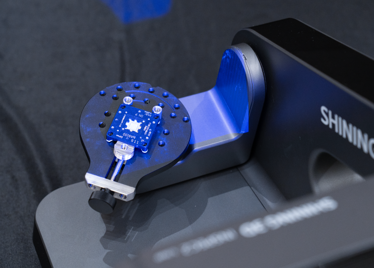
Accuracy, precision, resolution, and volumetric accuracy only become conclusive when they are measured against real geometry. SHINING 3D supports sample evaluation and inspection workflow validation for quality control teams, using the same certified reference discipline applied inside its accredited Accuracy Laboratory.
Download the SHINING 3D 3D Digitizing introduction brochure for the full metrology lineup, or request a sample scan and quotation at marketing@shining3d.com. Company details are available at www.shining3d.com.
Have Questions or Need More Details?
Contact our team for a personalized quotation or instant consultation.
Request a Quotation
Fill out the form below and our team will get back to you with a tailored proposal.
WhatsApp Direct Chat
Prefer to chat in real-time? Message us on WhatsApp for instant assistance & quick answers.
- Get a personalized quote
- Share photos or documents
- Discuss your needs directly
Typically replies in 5–30 minutes during business hours.