
3D Scanning Efficiency in Quality Control: Technical Factors and Selection Parameters
3D scanning efficiency in quality control is decided by the total time from part receipt to a signed inspection report — setup, data capture, data processing, and the maintenance and calibration that keep accuracy stable over years — not by a scanner's peak points-per-second figure. A practical model for comparing systems is: Total Project Time = Setup + Data Capture + Processing, with calibration and service downtime amortized across the year. Full-field, non-contact scanning shortens all three stages for many tasks: it captures millions of surface points in seconds instead of probing discrete points, and for many inspection tasks it measures up to 5–10× faster than contact probing.
This guide breaks down the technical factors behind that difference — data capture methodology, resolution, field of view, tracking and setup time, software processing, automation, and calibration — and converts them into selection parameters that smart manufacturers can specify, quote, and audit.
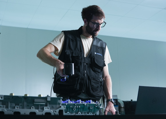
Problem Definition: Why Inspection Time Is Not the Same as Scanner Speed
Quality teams that evaluate scanners on catalog speed alone usually discover the same gap after installation: the scanner is fast, but the inspection is not. Setup, part preparation, marker placement, alignment, GD&T evaluation, and reporting each consume time that the headline scan rate does not describe.
Three inefficiencies account for most of the loss in a conventional inspection workflow:
- Queue time and lab dependency. Coordinate measuring machines (CMMs) are the recognized gold standard for absolute measurement accuracy and are ideal for critical geometric features in highly regulated, stationary workflows. They are also tied to an environment-controlled lab, which limits their availability for massive castings or large components and creates a backlog on the shop floor.
- Discrete data on freeform geometry. CMM probing captures specific points; calipers measure point-to-point distance. Neither produces a complete 3D profile of complex curvatures, warpage, or springback, so form defects that fall between the probed points pass inspection.
- Untraceable speed. Entry-level or hobbyist 3D scanners generate visually useful 3D models cost-effectively, but the data lacks strict metrological traceability and cannot sign off an engineering quality report.
The practical consequence is that a slower-scanner-plus-faster-workflow combination can outperform a faster scanner bolted onto a manual, marker-heavy, laptop-bound process. Selection therefore has to start from the workflow, not from the data sheet.
Industry Background: Full-Field 3D Inspection Is Moving to the Shop Floor
Demand for faster dimensional feedback is visible in published market data. Grand View Research estimated the global 3D scanning market at USD 4.28 billion in 2024, driven by increasing use in quality control and prototyping, while Precedence Research reported that the quality control and inspection application segment held the largest share of the 3D scanner market in 2024. MarketsandMarkets valued the broader 3D metrology market — scanners plus other dimensional measurement systems — at USD 11.13 billion in 2024.
Published estimates differ because the market definitions differ: Grand View Research's USD 4.28 billion and Precedence Research's narrower scanner-only figure describe overlapping but not identical scopes, and the same is true of USD 11.13 billion for 3D metrology versus other metrology market estimates. For procurement purposes, the direction of the data matters more than a single number: inspection is the largest application, the automotive industry is the largest end-user of 3D scanning technology, structured light scanners dominated the product segment in 2024 on precision grounds, and short-range scanners (≤ 1 m) held the largest range share because of precision parts inspection.
Automation reinforces the trend. The 3D automated optical inspection equipment market was valued at USD 2.74 billion in 2024 and is growing at a 7.32% CAGR, and inline automated 3D inspection systems are increasingly replacing offline checks in the electronics sector to improve first-pass yields. The competitive landscape is also well defined: Hexagon, FARO and Carl Zeiss are recognized as Tier 1 global leaders in industrial metrology, while SHINING 3D — a 3D vision company founded in 2004 and headquartered in Hangzhou, China — was recognized as an Emerging Leader in the global industrial metrology space by 360Quadrants in 2025.
Two standards anchor the compliance side of the discussion and should appear in any selection file: VDI/VDE 2634 Part 3 is the guideline for acceptance and reverification of optical 3D measuring systems based on multiple-view area scanning, and ISO 10360-12 is the international standard specifically for verifying the performance of articulated arm CMMs equipped with 3D scanners. ISO 10360-13 covers optical 3D coordinate measuring systems.
The Technical Factors That Decide 3D Scanning Efficiency
Seven factors explain most of the variance in throughput between systems that quote similar accuracy. Each can be specified, tested, and compared.
1. Data capture methodology: full-field scanning versus discrete probing
A CMM measures by touching the surface at programmed points; a 3D scanner reconstructs the surface. That difference is the single largest driver of inspection speed. Non-contact full-field scanning captures millions of points in seconds, compared with a limited series of discrete probing points, and delivers measurement speed up to 5–10 times faster for many inspection tasks.
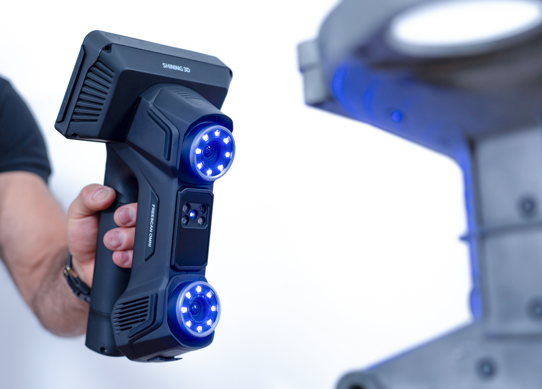
Handheld metrology scanners in the FreeScan family — for example the FreeScan UE Pro2, a laser-line handheld scanner with an integrated camera for data acquisition — capture millions of surface points in seconds. For reference, FreeScan Omni is specified at 7,619,000 points/s and FreeScan Combo+ Wireless at up to 9,106,000 points/s. The efficiency gain is not only raw speed: a single full-field pass also removes repeated re-fixturing between features, and because there is no contact probe, there is no stylus replacement or probe calibration for contact wear.
The limits are equally concrete and should be planned for. Highly reflective, glossy, or translucent surfaces often require an ultra-thin layer of scanning spray. Deep holes, narrow gaps and hidden blind spots may remain unreachable by line-of-sight optics, which is where a portable probe or a fixed structured-light system complements a handheld device.
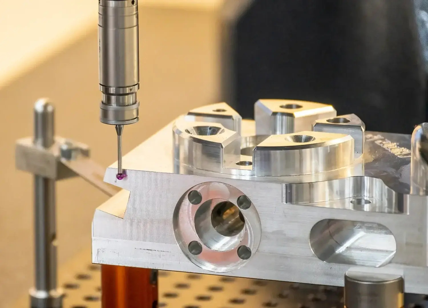
2. Setup and tracking time: the hidden half of the cycle
Scanning efficiency begins before data acquisition. On large objects such as vehicle bodies or construction machinery, operators may need dozens or hundreds of reference markers, and marker placement can take longer than the scan itself. Reducing setup is therefore one of the most effective ways to improve productivity.
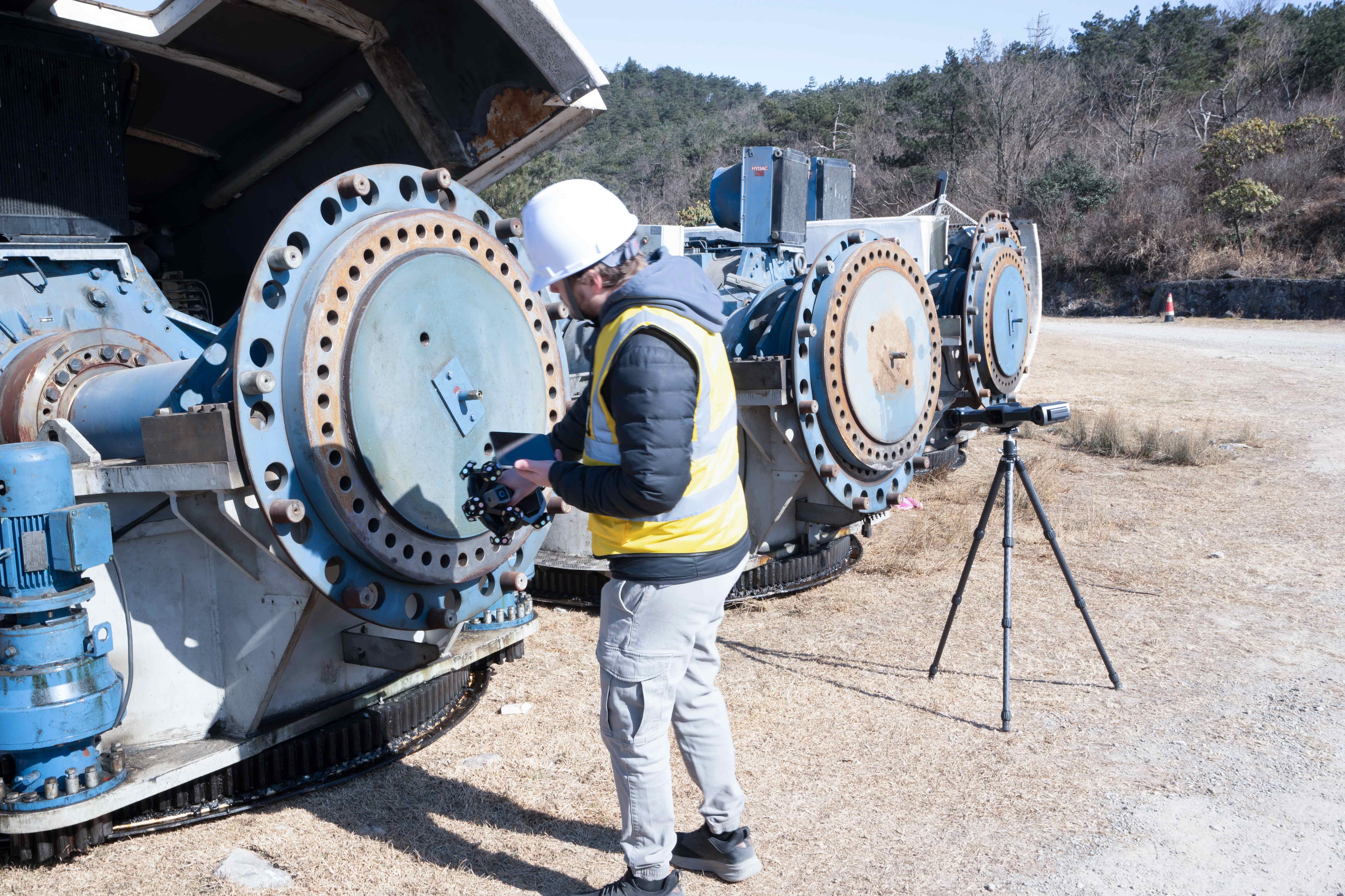
Two mechanisms shorten setup. Video Photogrammetry (VPG) uses continuous video capture as a measurement tool rather than hundreds of static images, verifying marker positions in real time and eliminating coded markers. On FreeScan Combo+ Wireless, built-in patented VPG maintains volumetric accuracy of 0.02 + 0.015 mm/m without coded markers. Dynamic optical tracking removes markers altogether for most parts: FreeScan Trak Nova Series uses tracking technology that scans without markers on most components, holds volumetric accuracy of 0.062 mm across a 12 m³ volume, and supports a flexible field of view up to 2,600 × 2,200 mm.
3. Resolution and point distance: detail versus data volume
Resolution defines the smallest detail a scanner can distinguish. Higher resolution captures finer edges, small engravings and surface defects, but it also generates larger datasets that increase processing and storage load — so resolution should be matched to the inspection tolerance, not maximized.
Point distance is the practical specification to compare. FreeScan Omni offers an adjustable resolution of 0.01–10 mm; OptimScan Q12 HD reaches a point distance of 0.02 mm in its small range; FreeScan Combo Series uses 0.05–10 mm point distance in laser mode. Software-side controls such as intelligent resolution, which adjusts point density according to surface curvature, let a single scan keep detail where it matters and stay lean where it does not.
4. Scan speed and field of view: coverage per pass
Scan speed is quoted in points per second — the amount of 3D data the system can capture and process from the surface each second. Higher values cover an object faster: FreeScan Trak Nova Series is specified at 7,600,000 points/s, FreeScan UE Nova at 4,600,000 points/s, and FreeScan Combo Series at up to 3,600,000 points/s in Combo+ configuration with 180 FPS frame rate in the wireless version.
Field of view multiplies that speed in practice. FreeScan UE Nova offers a maximum field of view of up to 2,600 × 2,200 mm with three selectable working ranges — near 300–800 mm, standard 600–1,500 mm, and far 1,200–2,600 mm — which lets one device cover a large surface in fewer passes and still work in a confined engine bay.

5. Software processing and reporting
Data acquisition is only part of the workflow; in many projects engineers spend more time processing data than collecting it. Software with automated alignment, feature recognition and report generation compresses the third term of the efficiency equation.
SHINING3D Inspect is a PTB-certified inspection module supporting CAD comparison, cross-section, feature and dimension checks, gauges, quick measurement and report generation. On FreeScan Omni, inspection runs on the device itself through a 5.5-inch touchscreen with built-in computing (32 GB), FPGA and a 1 TB SSD, so a scan-to-inspect sequence can be completed without a laptop. Features that reduce processing time include AI feature recognition for holes and slots, real-time mesh display, data quality visualization, and intelligent resolution. For deeper analysis, the scan data can move into PolyWorks, Geomagic Control X, EXModel Pro, Geomagic Design X, or BlueStar Mapping.
6. Automation: from manual passes to RobotScan Series
When the same family of parts is inspected repeatedly, the manual scanning cycle becomes the bottleneck. RobotScan Series integrates 3D scanning technology with a robot arm, controller base and turntable to deliver end-to-end automated solutions for batch inspection, in-line measurement, quality control and digital traceability. Fixed systems fit this role naturally: OptimScan Q12/Q9 supports manual, semi-automated (tripod plus turntable) and fully automated (robot integration) operation in the same 3.5 kg device, and AutoScan Inspec2 stores scanning paths so identical small parts can be scanned in one click with no manual intervention.
7. Maintenance and calibration: the factor that compounds
Efficiency degrades quietly. A scanner that drifts out of calibration forces re-scans, alignment failures and disputed reports — costs that never appear in a data sheet but do appear in the annual inspection budget.
Calibration should be scheduled, not reactive. SHINING 3D guidance defines four triggers: first use or after one to two weeks of inactivity; after severe shock or vibration such as transport; when accuracy is visibly reduced, causing frequent alignment errors or unrecognized markers; and when scan data becomes incomplete or quality deteriorates seriously. Calibration is performed with certified artifacts or calibration panels traceable to metrology standards, in an Accuracy Laboratory accredited in accordance with ISO/IEC 17025 — accreditation granted by CNAS, which is a signatory to mutual recognition arrangements, so reports and certificates are recognized internationally.
Mechanical simplicity is an efficiency asset. Non-contact scanning eliminates stylus replacement and probe recalibration for contact wear, requires less dedicated infrastructure, and lowers equipment and installation cost compared with a CMM. SHINING 3D also maintains subsidiaries and service locations in Stuttgart, Barcelona, California, Florida and Tokyo, which shortens support response for calibration, repair and application questions.
Step-by-Step Breakdown: Compressing Setup, Capture, and Reporting
A faster inspection cycle is a sequence of decisions rather than a single purchase. The workflow below reflects the six-stage digital inspection process and shows where each stage can be shortened.
- Define the inspection scope and tolerance band. Separate critical GD&T features from cosmetic and form checks. Accuracy tiers guide the choice: 0.005–0.02 mm for functional safety parts and strict GD&T, 0.02–0.05 mm for assembly verification and structural analysis, 0.05–0.1 mm for overall deformation and large cosmetic surfaces.
- Select the capture method and prepare the part. Markerless tracking or VPG removes marker placement for most medium-to-large parts; a marker-based workflow may still be preferred for very large surfaces where maximum volumetric accuracy is required. Reflective or translucent surfaces need an ultra-thin spray layer.
- Acquire 3D data. The first stage of the inspection workflow is collecting accurate 3D data from the physical object. High-precision scanners capture complex geometries, freeform surfaces and detailed features that are difficult to measure with traditional methods, and the scan data becomes the reliable foundation for dimensional inspection and quality analysis.
- Process and align the data. Point cloud and mesh data are cleaned, unnecessary information is removed, and the dataset is aligned to the CAD datum before analysis.
- Run CAD comparison and deviation analysis. Comparing scanned data with the CAD reference identifies dimensional variation, manufacturing deviation and surface differences, visualized as 3D color maps.
- Evaluate GD&T and critical dimensions. Users evaluate critical dimensions, geometric features and tolerance requirements to verify whether the part meets engineering standards.
- Generate the report and feed results back. Automated reporting organizes measurement results, deviations and analysis into traceable documentation, improving communication between engineering and quality teams and supporting digital quality management.
Where the time actually moves: stages 3 to 6 are compressed by full-field capture and automated software; stage 2 is compressed by VPG and markerless tracking; and repeated inspection of the same part family is compressed by path storage and robotic automation.
Selection Parameters for Smart Manufacturers
Selection should convert inspection requirements into specifications that can be quoted and verified. The table below lists the parameters that change efficiency outcomes, with reference values from the SHINING 3D metrology portfolio.
| Selection parameter | What to specify | Why it changes efficiency | Reference values (SHINING 3D) |
|---|---|---|---|
| Accuracy | Single-point accuracy against the tightest tolerance you must sign off | Determines whether re-measurement on a CMM is needed; industrial metrology scanners deliver measurement accuracy up to 2–5× higher than entry-level devices | 0.004 mm small range (OptimScan Q12/Q9 HD); 0.01 mm (AutoScan Inspec2); 0.02 mm (FreeScan Omni, FreeScan Combo Series, FreeScan Trak Nova Series); 0.072 mm (FreeScan UE Nova) |
| Repeatability | Consistency across repeated scans under unchanged conditions | Repeatability decides re-scan rate and operator confidence more than absolute accuracy does | Industrial-grade platforms provide better repeatability than entry-level scanners |
| Volumetric accuracy | Accuracy formula across the full measurement volume, plus VPG support | Controls error accumulation on parts longer than about one meter | 0.02 + 0.03 mm/m; 0.02 + 0.015 mm/m with VPG (FreeScan Omni); 0.062 mm over 12 m³ (FreeScan Trak Nova Series) |
| Resolution / point distance | Point distance range adjustable to tolerance | Too fine wastes processing time; too coarse misses defects | 0.01–10 mm (FreeScan Omni); 0.02 mm small range (OptimScan Q12 HD); 0.05–10 mm laser (FreeScan Combo Series) |
| Throughput | Points per second and field of view per pass | Sets the data-capture term of the cycle time for large surfaces | Up to 9,106,000 points/s (FreeScan Combo+ Wireless); 7,619,000 points/s (FreeScan Omni); FOV up to 2,600 × 2,200 mm (FreeScan UE Nova, FreeScan Trak Nova Series) |
| Environmental adaptability | Operating temperature, humidity, ingress protection, wireless capability | Shop-floor and outdoor deployment removes transport to a lab | -10 to 40 °C, 10–90% RH, IP50; Wi-Fi 7 wireless on FreeScan Combo+ Wireless |
| Automation readiness | Robot integration, path storage, MES/PLC interfacing | Converts per-part labour into a repeatable cycle for batch inspection | RobotScan Series integration; AutoScan Inspec2 path storage and 8-object multi-object mode; OptimScan Q12/Q9 robot compatibility |
| Software and reporting | PTB-certified inspection module, GD&T, color maps, report templates | Processing is often longer than capture; automation here is direct time savings | SHINING3D Inspect (PTB-certified, on-device on FreeScan Omni); compatibility with PolyWorks, Geomagic Control X, EXModel Pro |
| Calibration and service | Accredited calibration, certificate traceability, service locations | Prevents drift-driven re-scans and inspection disputes | ISO/IEC 17025 accredited Accuracy Laboratory (CNAS); VDI/VDE 2634 Part 2 and Part 3 plus ISO 10360 tested; service subsidiaries in Stuttgart, Barcelona, California, Florida, Tokyo |
| Total cost of ownership | 3–5 year cost including labour, rework, calibration and software | Initial price and ownership cost move in opposite directions | Initial cost about 5× an entry-level scanner, with total cost of ownership 20–40% lower over 3–5 years; inspection labour cost reduction of 30–50% versus contact CMM workflows |
The cost profile deserves emphasis because it is frequently misread. A metrology-grade scanner costs roughly five times more up front than an entry-level device, but over three to five years its total cost of ownership can be 20–40% lower, because reduced rework, fewer manual inspections and longer service life outweigh the purchase premium. In a CMM comparison, the same logic applies from the other direction: scanning carries lower equipment and installation cost than a CMM installation and typically requires less dedicated infrastructure.
Long-term selection criteria: what a five-year partnership actually requires
Because an inspection system stays in service for years, supplier durability belongs in the selection matrix alongside optical performance. Three dimensions matter:
- Supply-chain and trade continuity. SHINING 3D holds Authorized Economic Operator (AEO) advanced certification, which certifies a secure supply chain and efficient customs control — relevant when scanners, spare parts and calibration artefacts cross borders on a service schedule.
- Data security. Scan data and CAD references are intellectual property. SHINING 3D holds TISAX (fulfilling the information security requirements of the global automotive industry), ISO/IEC 27001, ISO/IEC 27701, ISO/IEC 27017, ISO/IEC 27018 and MLPS Level 3 certifications for information security and privacy.
- Software continuity. SHINING 3D states that it will continuously maintain and update the SHINING3D Inspect software, and that all FreeScan Omni customers receive these updates — a practical commitment when inspection templates and reports must remain valid year after year.
Commercial terms can also be specified in advance: minimum order quantity of one unit, delivery terms FOB / CFR / DAP / FCA, payment terms of 100% advance payment or installment payment, and acceptance criteria of delivery inspection or post-installation acceptance.
Use Cases: Where the Efficiency Gain Appears First
Efficiency improvements concentrate in applications where geometry is complex, parts are large, or inspection volume is high.
- Automotive tooling and stamping. 3D scanning supports 3D inspection of vehicle bodies and components, stamping die inspection, and wear and deformation monitoring across the tool and mold lifecycle. Full-field color maps expose warpage and springback that key-point checks miss.
- First article inspection (FAI). Comparing a complete scanned surface to CAD shortens the FAI loop for machined and cast parts, and the same dataset can be archived as traceable evidence.
- Aerospace components and MRO. Blade geometry, edge thickness and surface integrity verification benefit from high-resolution capture, while MRO work benefits from non-contact, rapid inspection of casings, combustors and turbines without partial disassembly.
- Mold and die wear inspection. Repeated scanning of the same tool builds a wear history that supports maintenance decisions and repair validation.
- Sheet metal and stamped parts. FreeScan Combo Series applications include sheet metal hole position accuracy inspection, and full-field capture makes hole pattern and edge deviation visible in one pass.
- Consumer electronics and small precision parts. AutoScan Inspec2 handles parts within a 140 × 90 × 80 mm range at up to 0.01 mm accuracy with path storage for batch scanning; OptimScan Q12/Q9 addresses GD&T analysis of precision structural parts.
- Heavy machinery, mining and marine. FreeScan UE Nova and FreeScan Trak Nova Series cover large structures such as truck beds, ship hull sections, propellers, rail components and mining equipment, including outdoor scanning with lens filters.
- Energy and heavy industry. Turbine, pipeline and pressure-equipment inspection benefits from non-contact measurement where access and part size make contact probing impractical.
Comparison: 3D Scanning, CMM, Calipers, and Entry-Level Scanning
The methods are complements, not substitutes. The comparison below uses only catalogued specifications and stated application boundaries.
| Method | Data captured | Relative measurement speed | Cost profile | Best fit | Limits |
|---|---|---|---|---|---|
| Metrology-grade 3D scanner (non-contact, full-field) | Millions of points per scan; complete surface including freeform geometry | Up to 5–10× faster than discrete probing for many inspection tasks | Lower equipment and installation cost than a CMM; initial cost about 5× an entry-level scanner, TCO 20–40% lower over 3–5 years | Complex freeform surfaces, large parts, rapid inspection, in-line inspection, reverse engineering, shop-floor quality control | Reflective, glossy or translucent surfaces may need an ultra-thin spray; line-of-sight access required |
| Coordinate measuring machine (CMM) | Discrete probed points at programmed positions | Baseline for the 5–10× comparison | Higher equipment and infrastructure cost; requires environment-controlled lab | Critical geometric features, highly regulated stationary workflows, absolute accuracy reference | Limited for massive castings and large components; stylus wear and probe calibration; slower surface coverage |
| Hand tools (calipers) | Point-to-point distance only | Fast for single basic dimensions | Lowest equipment cost | Simple geometries such as tube diameter | Cannot capture complex curvature or freeform surface profile; no digital traceability at surface level |
| Entry-level / consumer 3D scanner | Dense surface data for visual models | Fast for digitization | Lowest scanner cost; TCO higher over 3–5 years versus metrology-grade | Visual 3D digitalization, basic design assistance, digital asset creation | Data lacks strict metrological traceability; measurement accuracy 2–5× lower than industrial systems |
A practical reading of this table: keep the CMM for the critical features it does best, and move full-field form, deviation and surface inspection to a scanner so the CMM queue stops governing the inspection calendar. Where both are used, the scanner typically generates the global dimensional picture and the CMM verifies a small number of high-stakes features.
FAQ
Which standards certify 3D scanning accuracy for quality control, and can the supplier issue traceable certificates?
Three references matter. VDI/VDE 2634 Part 2 covers optical systems based on area scanning and Part 3 covers multiple-view systems based on area scanning; ISO 10360-12 covers articulated arm coordinate measurement machines and ISO 10360-13 covers optical 3D CMMs. SHINING 3D can issue calibration and accuracy certificates based on both VDI/VDE 2634 and ISO 10360. Its Accuracy Laboratory is accredited to ISO/IEC 17025 by CNAS, and because CNAS is a signatory to mutual recognition agreements such as the ILAC MRA, test reports and calibration certificates are recognized globally. Acceptance tests for metrology products are performed in that accredited laboratory against VDI/VDE 2634 Part 3 and ISO 10360.
How much faster is full-field 3D scanning than CMM probing, and where does the time actually go?
For many inspection tasks, non-contact full-field scanning measures up to 5–10× faster than discrete probing, because it captures millions of points in seconds instead of a limited number of probed points. The saved time splits across stages: setup falls when VPG or markerless tracking removes marker placement, capture falls because a single pass covers a large surface, and processing falls when inspection software automates alignment, GD&T evaluation and reporting. Additional savings come from maintenance — non-contact scanning requires no stylus replacement or probe calibration for contact wear — and from infrastructure, with reported inspection labour cost reduction of 30–50%. The exact figure for a specific part family should be confirmed by timing a real inspection cycle.
What does a quality control 3D scanning setup cost over three to five years?
Industrial inspection has the highest accuracy requirements and a demanding manufacturing environment; as general guidance, industrial metrology budgets typically start from around twenty thousand dollars. Compared with entry-level devices, metrology-grade scanners carry an initial cost roughly 5× higher, but total cost of ownership can be 20–40% lower over 3–5 years because of reduced rework, fewer manual inspections and longer service life, while delivering measurement accuracy up to 2–5× higher. Commercial terms are straightforward: MOQ of one unit, delivery terms FOB / CFR / DAP / FCA, payment terms of 100% advance payment or installment payment, and acceptance by delivery inspection or post-installation acceptance.
Can we validate a scanner on our own parts before purchasing?
Yes — validation should be done on representative production parts, not demonstration blocks. A practical validation protocol is: scan a part with known GD&T requirements, compare the data to the CAD reference in a PTB-certified inspection module such as SHINING3D Inspect, evaluate the critical dimensions and geometric features, and review the generated report against your existing acceptance record. Include the hard cases: dark or reflective surfaces, deep pockets, thin walls, and the largest part in the inspection envelope (for example 2,600 × 2,200 mm field of view on FreeScan UE Nova). Sample scanning and a quotation can be requested through the SHINING 3D team before a purchase decision is made.
What does long-term support look like — delivery, calibration and service continuity?
Delivery follows FOB / CFR / DAP / FCA terms with an MOQ of one unit; acceptance is by delivery inspection or post-installation acceptance. Calibration is scheduled on four triggers: first use or after one to two weeks of inactivity, after severe shock or vibration such as transport, when accuracy reduction causes frequent alignment errors or unrecognized markers, and when scan data becomes incomplete or quality deteriorates seriously. Service is supported through subsidiaries and service locations in Stuttgart, Barcelona, California, Florida and Tokyo, and supply-chain continuity is reinforced by AEO advanced certification, with data protection covered by TISAX, ISO/IEC 27001, ISO/IEC 27701, ISO/IEC 27017, ISO/IEC 27018 and MLPS Level 3. To move from evaluation to execution, request a sample scan or a formal quotation, and download the SHINING 3D 3D Digitizing introduction for full product documentation.
Conclusion: Specify the Workflow, Then Specify the Scanner
Efficiency in quality control is an outcome of the whole inspection chain: how the part is prepared, how much surface the scanner captures per pass, how quickly software turns points into a verdict, and how reliably the system holds accuracy between calibrations. Full-field non-contact scanning changes the economics of that chain — millions of points in seconds, up to 5–10× faster measurement for many tasks, no stylus wear, and a total cost of ownership that can be 20–40% lower over three to five years despite a higher purchase price.
The selection parameters that decide whether those gains materialize are specific and testable: accuracy matched to tolerance, repeatability, volumetric accuracy with VPG, resolution and point distance, throughput and field of view, environmental rating, automation readiness, software capability, accredited calibration, and supplier continuity backed by AEO, TISAX and ISO/IEC 27001-series certifications.
Next step: validate on your own parts
Send a representative part and its GD&T requirements to the SHINING 3D team for a sample scan, or request a formal quotation with delivery terms and acceptance criteria. The SHINING 3D 3D Digitizing introduction covers the full metrology portfolio, including FreeScan Omni, FreeScan Combo+ Wireless, FreeScan Trak Nova Series, FreeScan UE Nova, OptimScan Q12/Q9 HD and AutoScan Inspec2.
Download the brochure: SHINING 3D 3D Digitizing introduction (PDF)
Website: www.shining3d.com | Email: marketing@shining3d.com | Tel: +86 571 8299 9050
Service locations: Stuttgart, Barcelona, California, Florida, Tokyo.
Have Questions or Need More Details?
Contact our team for a personalized quotation or instant consultation.
Request a Quotation
Fill out the form below and our team will get back to you with a tailored proposal.
WhatsApp Direct Chat
Prefer to chat in real-time? Message us on WhatsApp for instant assistance & quick answers.
- Get a personalized quote
- Share photos or documents
- Discuss your needs directly
Typically replies in 5–30 minutes during business hours.