
Thailand Mold Inspection: Metrology 3D Scanner Deployment
Deploying a metrology 3D scanner for high-precision mold inspection in Thailand comes down to six decisions: which tolerances the mold has to prove, which scanner configuration matches mold size and surface condition, what the shop-floor inspection point physically looks like, how accuracy is validated before sign-off, what scan-to-CAD workflow the quality team will run every working day, and how calibration, software and support continuity are secured for the years after installation. The measurement principle does not change between countries; the execution risk sits in environment, workflow and long-term support.
This guide is written for the team that has already approved the investment: the tooling engineer, quality manager or plant manager in a Thai mold and die shop who now has to make a 3D scanning system produce inspection reports on a shop floor rather than in a metrology laboratory. It focuses on handheld, portable and wireless scanning for on-site and shop-floor inspection, because that is where most mold verification work actually happens.
What High-Precision Mold Inspection Has to Prove
A mold is the forming tool that transfers its own geometry into every part produced from it, so its accuracy and reliability directly affect end-product quality and production efficiency. Traditional inspection methods are limited in two specific ways: they struggle to capture full surface data on complex geometry quickly, and they are weak at quantifying microscopic deformation and hidden defects. Non-contact 3D scanning addresses both by building a high-accuracy, full-field digital record of the mold, which then supports design validation, process optimization, quality control and maintenance decisions from one data source.
In a mold shop's machining stage, that record supports three concrete checks: machining allowance analysis before final finishing, datum alignment verification, and milling tool path validation. During first-article and series inspection it supports full geometry verification, material thickness analysis, automated inspection routines, and flush-and-gap evaluation. The value does not stop at a pass or fail decision — the resulting data is traceable, so repair records, supplier validation archives and lifecycle quality data remain available for later audits and for the next build of the same tool.
Why calipers and CMM time are not enough on their own
A caliper measures point-to-point distance very efficiently, and it remains the right tool for simple geometry such as a tube diameter. What it cannot do is capture the comprehensive 3D profile of complex curvature or an intricate free-form surface. A coordinate measuring machine (CMM) is the recognised reference for absolute accuracy and critical geometric features, but it is tied to an environment-controlled laboratory and is limited when the workpiece is a massive casting or a large mold body that should not leave the shop floor. A metrology-grade 3D scanner sits between the two: it brings measurement capability to the factory floor, captures millions of data points in seconds instead of a handful of discrete probed points, and produces colour deviation maps that are readable by machinists as well as by quality engineers. For many inspection tasks this is 5–10 times faster than point-based checking, and there is no stylus wear or probe calibration to manage. The trade-off is real and should be planned for: on highly reflective, glossy or translucent surfaces, a thin layer of scanning spray may still be required unless the chosen light source can handle those materials.
Accuracy, Precision, Resolution and Volumetric Accuracy in Mold Work
Mold tolerances are usually argued in single features, but mold geometry is large, which makes one more number decisive: volumetric accuracy. Four definitions should be settled before a purchase order, because they determine whether the scanner can sign off the tool.
- Accuracy is how closely a measured result matches the true dimension. If a 100.00 mm feature measures 100.02 mm, the error is 0.02 mm; smaller error means higher accuracy.
- Precision, or repeatability, is how consistently the same measurement reproduces under unchanged conditions. Five consecutive readings of 100.02, 100.02, 100.03, 100.02 and 100.02 mm show excellent repeatability even though the readings are slightly offset from the true value — a scanner can be precise without being perfectly accurate.
- Resolution is the smallest detail a scanner can distinguish. Higher resolution captures finer edges and engravings, but it does not automatically mean higher dimensional accuracy, and it increases dataset size and processing load.
- Volumetric accuracy describes accuracy across a larger scanning volume. Industrial scanners often specify it as a formula such as 0.02 mm + 0.015 mm/m, so a 2 m object gives 0.02 + (0.015 × 2) = 0.05 mm of maximum expected error over its full length.
For a mold shop this matters in practice. A small insert may be judged on a 0.005–0.02 mm tolerance where strict GD&T inspection and precision reverse engineering are involved. A medium mold body typically falls in the 0.02–0.05 mm band used for assembly verification and structural analysis, which is where handheld scanning is comfortable. Overall deformation and surface deviation mapping on large structures sit in the 0.05–0.1 mm band. The cumulative error over a long mold base can be reduced with global markers and video photogrammetry (VPG), which builds a high-accuracy target framework around the part and controls global accuracy when scanning objects several metres long.
Which Scanner Configuration Fits the Mold
SHINING 3D (Shining 3D Tech Co., Ltd.), a 3D vision company founded in 2004 and headquartered in Hangzhou, China, offers four configuration families that map onto different mold inspection jobs. Selection should follow object size, tolerance and surface condition — not the other way round.
Standalone wireless handheld: the on-site default
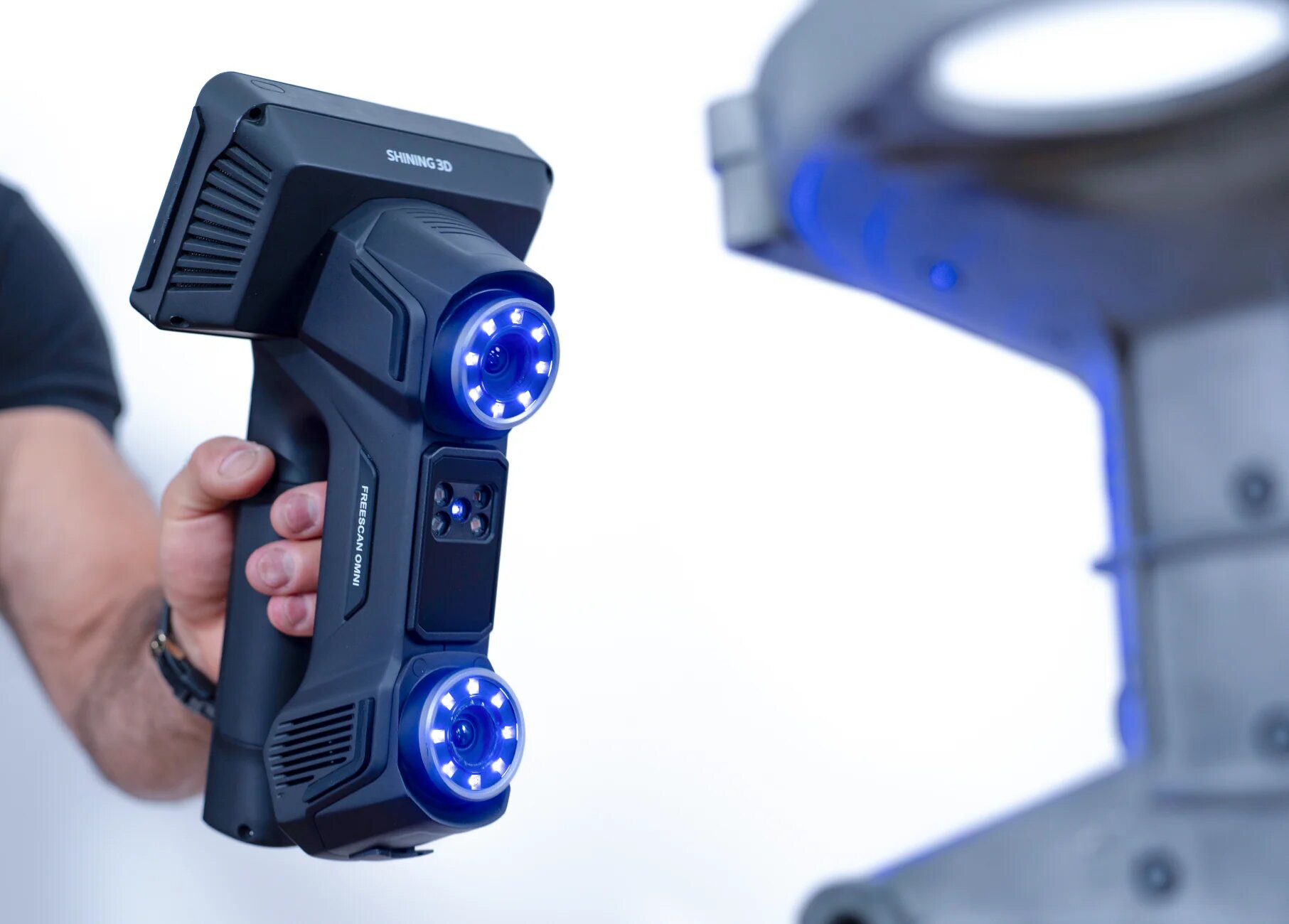
The FreeScan Omni is a wireless standalone metrology handheld 3D scanner with an accuracy of 0.02 mm, certified to VDI/VDE 2634 Part 3 and ISO 10360. It runs without a computer tether, with integrated inspection software on the device, so scanning and 3D inspection can be completed entirely on the scanner at the mold. Blue laser handles complex, dark and reflective surfaces, which is the normal condition of a polished or nitrided cavity. The FreeScan Omni Lite shares the same chassis, accuracy and core scanning performance, and can later be expanded with dedicated modules — on-device inspection, VPG for volumetric accuracy on large objects, and AI feature recognition for common geometric features — making it a deliberate upgrade path rather than a dead end.
Dynamic tracking: medium-to-large mold bodies without markers
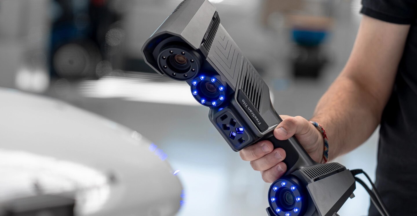
The FreeScan Trak Nova is a wireless multi-functional dynamic tracking and scanning system that delivers markerless 3D scanning of medium-to-large objects at 0.02 mm accuracy, also certified to VDI/VDE 2634 Part 3 and ISO 10360. Its handheld component, the FreeScan UE Nova, detaches and works as a standalone handheld laser scanner. Markerless optical tracking is the single biggest time saver in mold work: placing dozens or hundreds of markers on a large mold base can take longer than the scan itself, so removing that step changes the economics of every job.
Fixed blue-light structured light: micro-features and small inserts
The OptimScan Q12/Q9 HD is a fixed blue structured-light 3D inspection scanner built on a four-camera system with dual scanning ranges and Monocular-Stereo Fusion. The HD variants reach 0.004 mm accuracy and 0.02 mm point distance, while the standard Q12/Q9 models specify 0.005 mm; Q12 and Q9 refer to 12 MP and 9 MP camera resolution. These are the systems for razor-thin blade edges, tiny holes and micro-connectors, and they are typically used where a fixture and a controlled local light environment are acceptable. A blue-light metrology 3D scanner of this class is the correct answer when micro-detail capture outranks mobility.
Handheld laser and hybrid light: difficult surfaces, flexible positioning
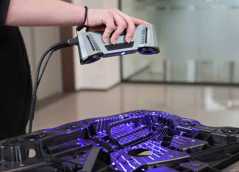
The FreeScan Combo series adds handheld options with laser and hybrid light sources, delivering reliable results on reflective, dark or irregular surfaces and fast data acquisition in the positions a fixed system cannot reach. Where a cavity has deep holes, narrow gaps or hidden blind spots that no line of sight reaches, the practical answer is to pair the scanning system with a portable probe rather than to force the scanner into geometry it cannot see.
A Six-Stage Deployment Sequence for a Thai Mold Shop
Stage 1 — Define the inspection scope and tolerances
Object size is the first filter. Small parts below roughly 500 mm need systems focused on intricate cavities and fine geometry; medium-to-large components from 500 mm to 2500 mm have complex surfaces and large curved areas that suit portable scanning; extra-large structures above 2500 mm need an expansive tracking volume to hold consistency across the whole part. Write down the tolerance band for each mold family, because it decides whether a 0.02 mm handheld system is sufficient or whether a 0.004–0.005 mm fixed system is required for the insert work.
Stage 2 — Choose the configuration and the light source together
Blue laser projection suits shiny, reflective, dark or black surfaces such as machined alloys and sheet metal without developer spray, and it tolerates ambient light well. Blue structured light with LED projection is the better route for fine detail, sharp edges and small precision components. If the mold work is dominated by large bodies handled by two operators, dynamic tracking wins; if it is dominated by small inserts measured at a bench, fixed structured light wins. Many shops need both and should plan the split deliberately.
Stage 3 — Prepare the shop-floor inspection point
A factory-floor installation has to be protected against vibration, temperature fluctuation, dust and variation in ambient light. Structured-light fringe projection is the most sensitive to strong ambient light, so the bench area should be shielded from direct sunlight and from inspection lamps that throw hard shadows across the cavity. The scanner itself needs a stable surface and a trained operator, with no heavy vibration during scanning. Practical additions that cost little and pay back quickly: a dedicated mould trolley at working height, a power point that does not force cable runs across walkways, and a marker-free workflow wherever the part allows it so nothing has to be cleaned off before the next machining pass.
Stage 4 — Validate accuracy and complete acceptance
Accuracy validation happens before production data is trusted. SHINING 3D can issue calibration and accuracy certificates based on both VDI/VDE 2634 and ISO 10360 for its metrology-grade scanners. The company's accuracy laboratory is accredited to ISO/IEC 17025 by CNAS, and because CNAS is a signatory to mutual recognition arrangements such as the ILAC MRA, its test reports and calibration certificates are recognised globally — a point that matters when a Thai mold shop has to show traceability to an overseas customer or an automotive audit. The laboratory is certified to test in compliance with VDI/VDE 2634 Part 2 and Part 3, and the verification protocols align with ISO 10360-12 and ISO 10360-13. Acceptance criteria commonly used are delivery inspection and post-installation acceptance; a repeatability run — scanning one reference mould feature five times under unchanged conditions — is the simplest way to confirm the installed system behaves as the certificate says.
Stage 5 — Build the scan-to-CAD workflow
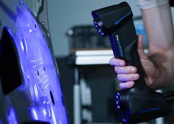
Data acquisition is only the first quarter of the job. A professional inspection workflow runs in four steps: capture the part; process and align the point cloud or mesh; compare against CAD with deviation analysis, dimensional inspection and GD&T evaluation; then generate a traceable report. Alignment quality decides everything downstream, so the reference scheme — datums, best-fit versus feature-based alignment — should be agreed with the tooling engineer before the first production report. For software, SHINING 3D scanning data is commonly processed in SHINING3D Inspect, PolyWorks, GOM Inspect or Geomagic Control X, so the existing software stack is usually not a barrier.
Stage 6 — Train operators and set the routine
Scanning efficiency is not just points per second. A practical model is: total project time = setup + data capture + processing. Setup includes marker placement and fixturing; capture depends on scan speed and field of view; processing depends on resolution and dataset size. On a large mold base, setup can exceed capture time, which is exactly why marker-free tracking and standalone wireless operation change the daily routine. Resolution should be matched to the inspection tolerance rather than maximised, because finer point distance means larger datasets and longer processing. Two trained operators per shift, a fixed reference part for weekly checks, and one agreed report template are usually enough to make the workflow repeatable.
Configuration Comparison for Mold Inspection Deployment
The table summarises the four configurations above using only manufacturer-stated specifications. Accuracy figures are per model and should always be read together with the certificate scope applicable to the delivered unit.
| Configuration | Example models | Stated accuracy | Best-fit mold work | Deployment note |
|---|---|---|---|---|
| Standalone wireless handheld | FreeScan Omni / FreeScan Omni Lite | 0.02 mm; VDI/VDE 2634 Part 3 and ISO 10360 certified | Small to large molds; on-site and shop-floor inspection of cavities and cores | No computer tether; inspection on the device; Omni Lite expands later with inspection, VPG and AI feature modules |
| Dynamic optical tracking | FreeScan Trak Nova, with detachable FreeScan UE Nova | 0.02 mm; VDI/VDE 2634 Part 3 and ISO 10360 certified | Medium-to-large mold bodies and assemblies scanned without markers | Marker-free workflow removes the largest setup cost; the handheld unit also works standalone |
| Fixed blue structured light | OptimScan Q12/Q9 HD (0.004 mm); OptimScan Q12/Q9 (0.005 mm) | 0.004–0.005 mm; 0.02 mm point distance on HD | Small inserts, sharp edges, micro-holes and fine mold detail | Requires fixturing and a controlled local light environment; highest detail, lowest mobility |
| Automated cell | RobotScan series | Follows the integrated scanner model | Batch and in-line inspection, repeat measurement of the same mold family | Robot arm, controller base and turntable; line-level integration uses protocols such as OPC UA or Profinet |
Mold-Shop Use Cases After Installation
Once the system is accepted, five use cases usually justify it within the first year. These are application patterns, not claims about any specific customer installation.
- New mold first-article verification: full geometry comparison against CAD, thickness analysis and flush-and-gap checks before the tool is released to production.
- Machining allowance and datum checks: scan between roughing and finishing to confirm allowance and confirm the datum scheme before a finishing pass.
- Wear, repair and weld verification: measure a worn cavity or a repaired area and compare it with the original digital record instead of relying on the last part produced.
- Legacy mold reverse engineering: capture an existing tool or obsolete insert as a high-density point cloud, reconstruct an editable CAD model, then reproduce it by CNC machining or additive manufacturing.
- Automation scale-up: when volume grows, the same scanner families can be integrated into a robot cell for repeat batch or in-line 3D inspection, converting sampling into fuller verification and strengthening traceability.
The Long-Term Question: Choosing a Metrology 3D Scanner Manufacturer
At the execution stage, the manufacturer matters as much as the specification, because a mold shop keeps the system for years and its data has to remain defensible. Four continuity factors deserve scrutiny before contract signature.
Calibration and certificate continuity. Certificates must be reissued on a schedule and remain comparable year over year. An ISO/IEC 17025 accredited laboratory operating under VDI/VDE 2634 and ISO 10360 protocols, with international recognition through CNAS and the ILAC MRA, is what makes that possible without sending the system abroad for months.
A real upgrade path. Capability should be extendable without replacing hardware. The FreeScan Omni Lite module approach — adding on-device inspection, VPG or AI feature recognition as needs evolve — and the detachable design of the FreeScan Trak Nova are concrete examples of that principle.
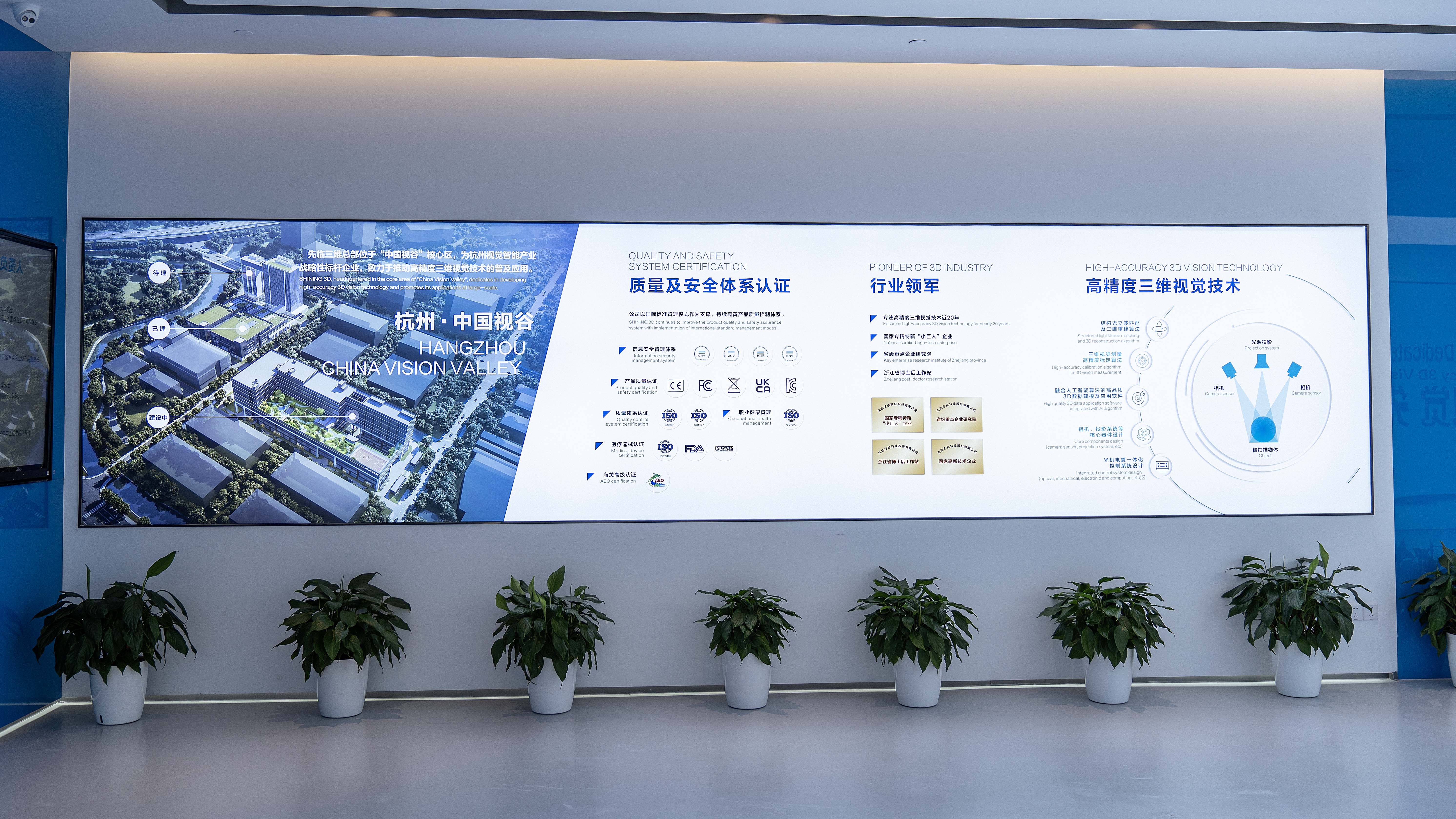
Service reach and supply continuity. SHINING 3D maintains subsidiaries in Stuttgart, Barcelona, California, Florida and Tokyo alongside its Hangzhou headquarters, and holds Authorized Economic Operator (AEO) advanced certification, which supports secure and efficient customs clearance for imported equipment. For a Thai buyer importing a metrology system, predictable logistics and a regional technical contact are part of the measurement chain, not an afterthought.
Organisational stability and quality systems. SHINING 3D was established in 2004, occupies a facility of nearly 140,000 m², employs 1,367 people including 533 engineers, and holds more than 330 authorised patents and 230 software copyrights. Its management systems include ISO 9001, ISO 14001, ISO 45001 and ISO 13485, with MDSAP and KGMP for medical programmes, plus CE, FDA and FCC product compliance and information-security certifications including TISAX and ISO/IEC 27001. For a mold shop, the practical meaning is straightforward: a supplier that can document process control is more likely to still be issuing comparable calibration certificates in year five.
Pre-Sign-Off Deployment Checklist
- Mold families listed by maximum dimension and tolerance band, with the required accuracy tier recorded per family.
- Surface conditions documented — polished, nitrided, textured, coated — with the light source and any spray requirement decided in advance.
- Inspection point defined: bench or trolley, ambient light shielding, vibration isolation, dust control and cable-free operation where possible.
- Certificate scope checked against VDI/VDE 2634 and ISO 10360, with the accredited laboratory and its recognition status confirmed.
- Acceptance method agreed: delivery inspection and/or post-installation acceptance, plus a repeatability run on a known feature.
- Reference part and alignment scheme fixed, so reports are comparable month to month.
- Operator training completed and calibration re-verification interval written into the maintenance plan.
Frequently Asked Questions
Which standards should a mold-inspection 3D scanner certificate reference?
Look for VDI/VDE 2634 and ISO 10360. SHINING 3D can issue calibration and accuracy certificates based on both standards for its metrology-grade 3D scanners. The accuracy laboratory is accredited to ISO/IEC 17025 by CNAS, a signatory to mutual recognition arrangements including the ILAC MRA, so test reports and calibration certificates are recognised globally. Testing is performed in compliance with VDI/VDE 2634 Part 2 and Part 3, and verification protocols align with ISO 10360-12 and ISO 10360-13.
Can a portable 3D scanner handle both small inserts and large mold bodies?
Usually two configurations are used rather than one. For small parts below about 500 mm, a fixed blue structured-light system such as OptimScan Q12/Q9 HD at 0.004 mm accuracy is the better fit for fine detail. For medium-to-large components from 500 mm to 2500 mm and beyond, markerless dynamic tracking such as FreeScan Trak Nova at 0.02 mm holds accuracy across the larger volume, and video photogrammetry can control global accuracy over long parts. Deep holes and narrow gaps that no line of sight reaches are best captured with a portable probe paired with the scanner.
What purchasing terms and budget expectations apply to a metrology 3D scanner?
Stated terms for SHINING 3D metrology systems include a minimum order quantity of one unit, delivery terms of FOB, CFR, DAP or FCA, acceptance by delivery inspection or post-installation acceptance, and payment by 100% advance payment or instalment payment. On budget, SHINING 3D's published selection guidance notes that industrial inspection has the highest accuracy requirements and a harsh manufacturing environment, with budgets typically starting from twenty thousand US dollars.
How do we validate the scanner on our own molds before a full rollout?
Start with one representative mold family and a known reference feature. Scan that feature five times under unchanged conditions to test repeatability, compare the result against the CAD model and against any existing measurement record, and check the deviation against the tolerance band the mold must meet. Because the minimum order quantity is one unit, a shop can begin with a single system, prove the workflow on real tools, and add fixed or automated configurations later when the volume of inserts or the inspection cycle time justifies them.
How do you choose a long-term metrology 3D scanner manufacturer for industrial inspection?
Judge the supplier on what must still be true in year five: a calibration laboratory accredited to ISO/IEC 17025 that issues VDI/VDE 2634 and ISO 10360 certificates recognised internationally, a documented upgrade path such as the FreeScan Omni Lite modules or the detachable FreeScan Trak Nova handheld, regional service reach through subsidiaries, and supply continuity supported by AEO-certified customs processes. SHINING 3D combines these with an in-house portfolio spanning handheld, tracking, fixed and automated systems, which lets a mold shop scale the same measurement ecosystem as its inspection scope grows.
Planning a deployment in Thailand? The SHINING 3D 3D digitizing introduction covers the full handheld, tracking, fixed and automated range in one document, and is a practical starting point for a technical review with your tooling and quality teams.
Conclusion
A metrology 3D scanner deployment for high-precision mold inspection in Thailand is a sequencing problem more than a specification problem. Get the tolerance band and object size right, match the light source to the actual cavity surface, prepare a realistic shop-floor inspection point, validate accuracy with a certificate that an auditor will accept, and build the alignment and reporting routine that turns scan data into a defensible mold record. Then confirm the long-term side: calibration continuity, module upgrades, service reach and customs-ready supply. Handled in that order, handheld and portable 3D scanning stops being a purchase and becomes the shop's measurement reference. SHINING 3D publishes its full range and contact details at SHINING 3D; the company can be reached at marketing@shining3d.com, +86 571 8299 9050, or No. 1398, Xiangbin Road, Wenyan, Xiaoshan, Hangzhou, Zhejiang, China, 311258.
Have Questions or Need More Details?
Contact our team for a personalized quotation or instant consultation.
Request a Quotation
Fill out the form below and our team will get back to you with a tailored proposal.
WhatsApp Direct Chat
Prefer to chat in real-time? Message us on WhatsApp for instant assistance & quick answers.
- Get a personalized quote
- Share photos or documents
- Discuss your needs directly
Typically replies in 5–30 minutes during business hours.