
FreeScan UE Pro2 vs. CMM for Quality Control: A Head-to-Head Decision Guide
A practical comparison for quality teams deciding between handheld blue-laser scanning and contact measurement.
A quality team rarely chooses a measurement method in isolation. The decision usually arrives as a queue: the CMM is booked for a week of first article inspection, a new sheet metal family is waiting for fixture design, and a supplier wants full-surface deviation data that a touch probe cannot produce quickly. The real question is not whether a CMM or a handheld 3D scanner is better in general. It is which method should own which measurement, and where the two should work together.
This guide compares the SHINING 3D FreeScan UE Pro2, a handheld blue-laser 3D scanner, with a coordinate measuring machine (CMM) across the decisions quality engineers actually face: first article inspection, GD&T evaluation, shopfloor inspection, mold and sheet metal work, MRO, and automated in-line inspection.
The short answer
For most quality teams, the practical answer is a split. Use the FreeScan UE Pro2 where full-surface geometry, portability, and material adaptability matter. Keep the CMM where contact-based arbitration of tight-tolerance regular features is required, or where a contract or customer standard names CMM measurement as the acceptance method. The rest of this guide explains how to draw that line for your parts, your tolerances, and your shopfloor.
What each system actually measures
The CMM measurement model
CMM measurement is a contact process. A probe touches discrete points on the part, and the machine calculates coordinates from the probe position. The strength of this model is discipline: a well-programmed CMM follows a defined path, returns values for specific features, and is widely accepted as a reference method for regular geometry and tight tolerances.
The limitation is structural rather than a defect. A CMM measures the points it is programmed to touch. Freeform surfaces, thin walls, deep pockets, and large parts require either dense point strategies that take time or a measurement plan that samples rather than covers. Fixturing and part access also shape what can be reached. None of this makes a CMM inaccurate; it defines the kind of question a CMM answers well.
The FreeScan UE Pro2 measurement model
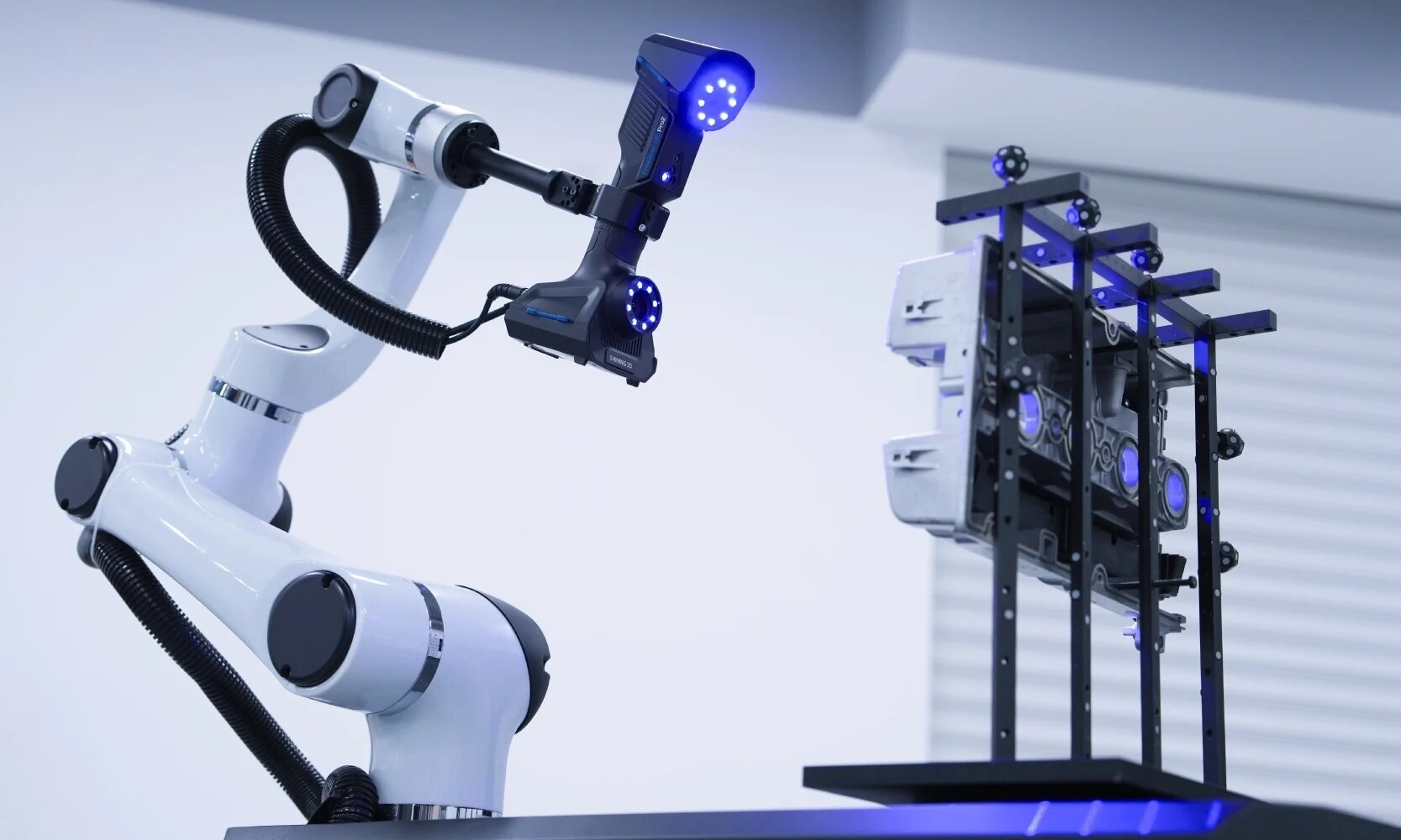
The FreeScan UE Pro2 is a handheld blue-laser 3D scanner. SHINING 3D's RobotScan UE Pro2 configuration uses handheld blue-laser scanning technology with strong adaptability to black, shiny, and reflective surfaces, and it is documented for small and medium-sized sheet metal parts, casting housings, machined parts, and mold components. The configuration supports wireless and wired connectivity for flexible on-site integration, and SHINING 3D positions it as an automation optical measurement solution with a balance of accuracy and efficiency.
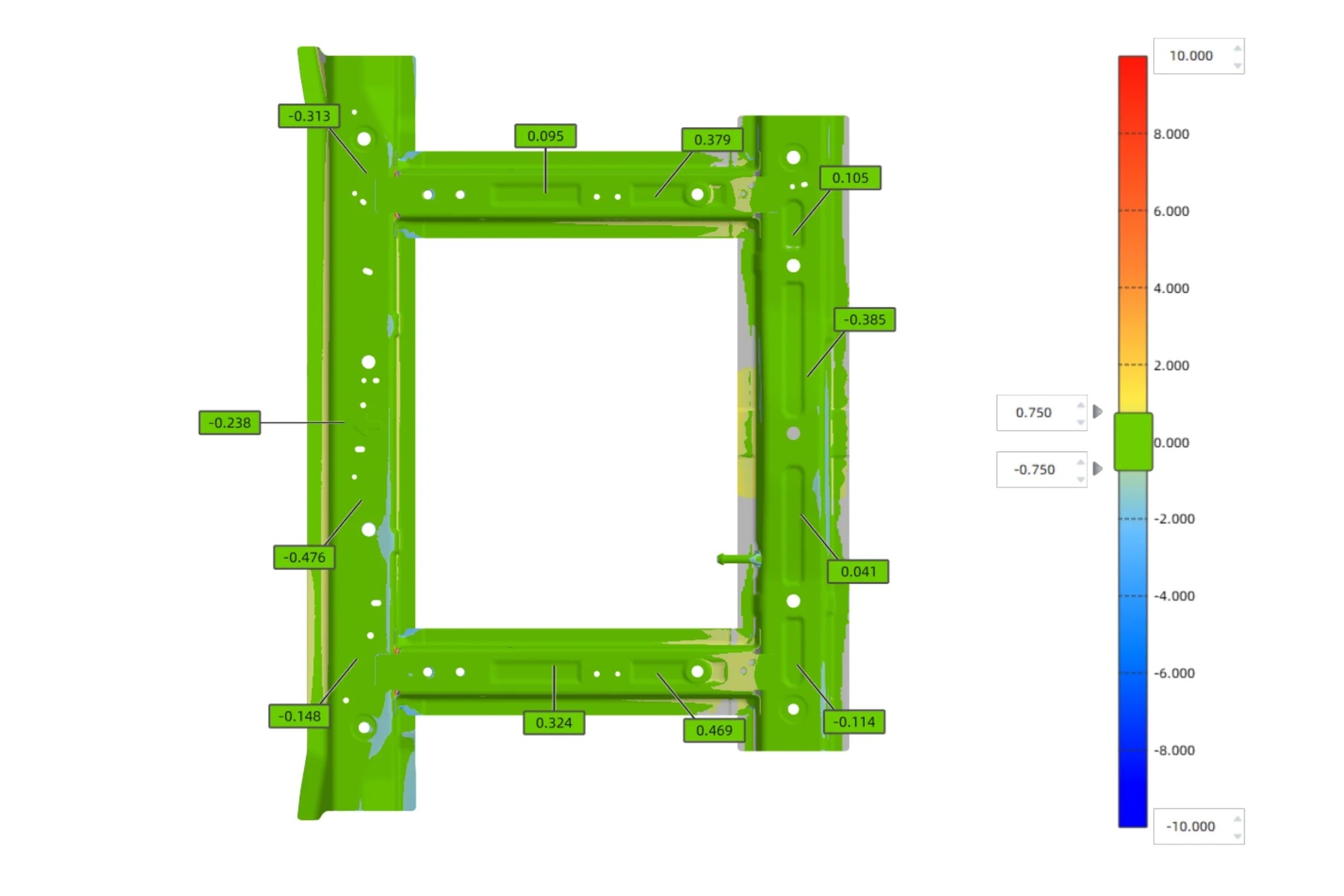
That description points to the operational difference. The scanner captures surface geometry as a dense data set rather than a sequence of touched points. The operator moves the device around the part, and the result is a full-field model that can be compared with CAD, sectioned, color-mapped, and used for GD&T evaluation in inspection software. The trade-off is that optical scanning depends on line of sight and surface response, and its accuracy statement must be read from the specific configuration's calibration and acceptance documentation.
Head-to-head comparison table
The table below compares the two approaches on the factors that usually decide a quality-control purchase. The FreeScan UE Pro2 column uses documented characteristics of the UE Pro2 configuration. The CMM column describes the established contact-measurement model. The final column shows what a quality team should verify before committing.
| Decision factor | FreeScan UE Pro2 (documented) | CMM (established measurement model) | What to verify |
|---|---|---|---|
| Measurement principle | Handheld blue-laser optical scanning captures surface data. | A contact probe touches discrete points and calculates coordinates. | Does the decision need full-surface coverage or feature-specific values? |
| Surface coverage | Full-field surface capture in one scanning workflow. | Programmed points and features along a defined probe path. | Are there unprogrammed areas where a deviation could hide? |
| Documented part fit | Small and medium-sized sheet metal parts, casting housings, machined parts, and mold components. | Regular geometry, tight-tolerance features, and reference dimensions. | Which part families dominate your inspection queue? |
| Setup and fixturing | Handheld operation; effort shifts toward scanning strategy, alignment, and part access. | Probe path programming, part setup, and fixtures are central to the workflow. | How much time and cost go into programming and fixtures today? |
| Environment and portability | Wireless and wired connectivity support on-site and shopfloor use. | Typically operated in a controlled metrology environment. | Can the part come to the measurement room, or must measurement go to the part? |
| Material response | Blue laser is described as adaptable to black, shiny, and reflective surfaces. | Contact probing is largely material-independent but can mark soft surfaces. | Do your materials need surface preparation for optical scanning? |
| Deviation and GD&T output | Full-surface deviation maps, sections, and feature evaluation through inspection software. | Feature-based dimensional results tied to the probe program. | Does the customer need a color map, a feature table, or both? |
| Automation path | Can be integrated into RobotScan automation configurations. | Program-based repeat measurement with part handling and fixturing. | What part-handling and cycle-time assumptions does automation require? |
| Traceability and strongest ownership | Confirm the calibration certificate and acceptance test for the exact configuration; SHINING 3D operates an ISO/IEC 17025 accredited accuracy laboratory. Strongest for FAI screening, shopfloor work, sheet metal, molds, MRO, and complex surfaces. | Established metrology practice with calibration and controlled programs. Strongest for final arbitration of critical regular features and contract-specified checks. | Which method should own the acceptance decision for each feature? |
Where the FreeScan UE Pro2 fits better
First article inspection on complex parts
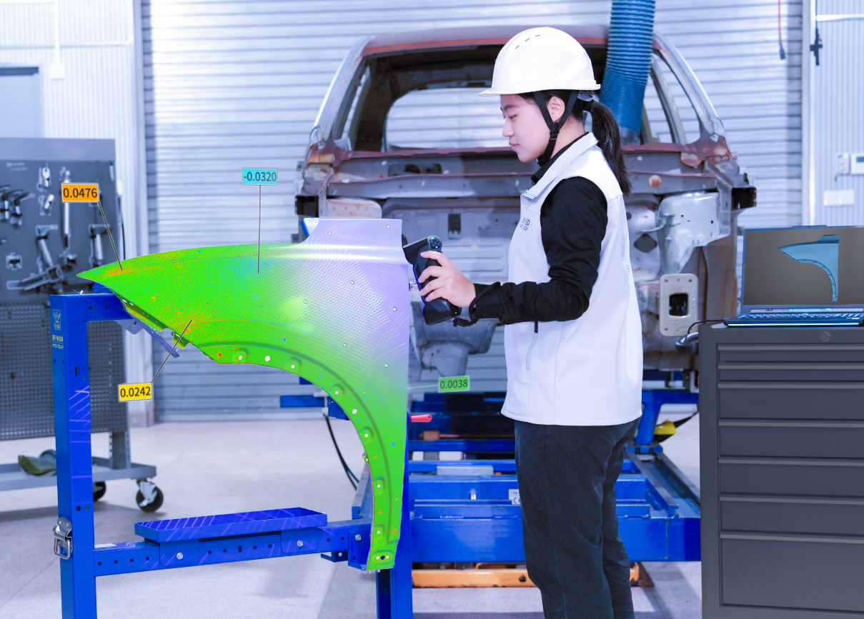
First article inspection asks a simple question: does the first part match the design? The answer is often more than a list of dimensions. A CMM can confirm programmed features; a handheld scan can show the entire surface, including areas that were never programmed. For parts with freeform surfaces, blends, thin walls, or asymmetric geometry, the full-field view reduces the risk of missing a deviation between touch points.
The practical rule is to use the scanner for the whole-part screen, then use the CMM to arbitrate the features that carry the tightest tolerances or contractual weight. That sequence turns a 3D scanner for first article inspection into a filter: it tells the quality team where to spend CMM time instead of spending it everywhere.
Shopfloor and on-site inspection
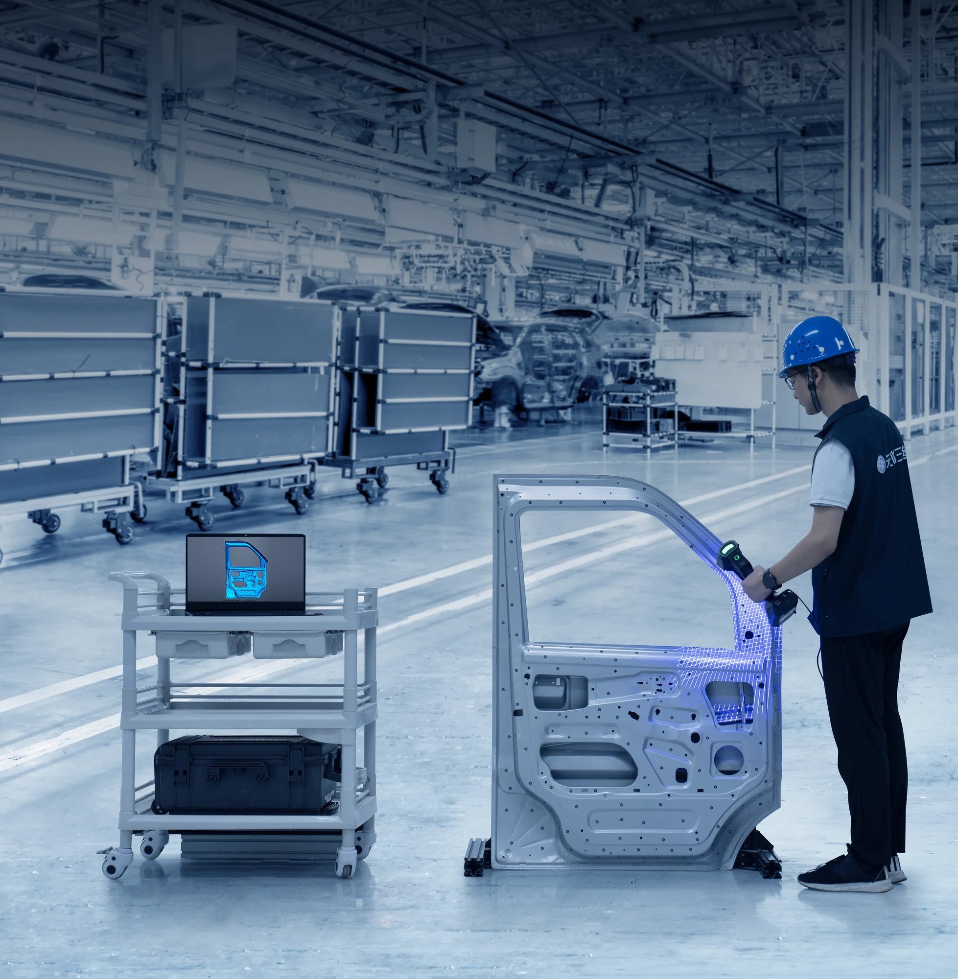
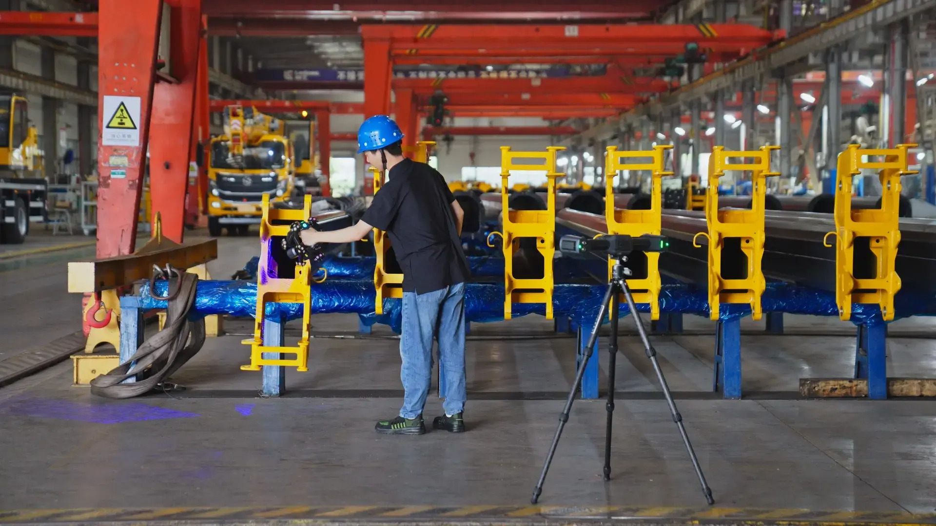
The UE Pro2's wireless and wired connectivity and handheld format support measurement near the production line rather than in a metrology room. That matters when the part is large, awkward to move, or needed back in the process quickly. Documented SHINING 3D cases show the same operational logic in other configurations: a mining and heavy-industry team used the FreeScan Omni for on-site scanning of large slurry pump components; a construction machinery manufacturer used portable scanning for complex exterior panels and fixture inspection; and a shipyard scanned an aluminum-alloy hull to quantify welding deformation.
These cases do not prove what the UE Pro2 will do on your parts, but they show why portability changes the inspection sequence. When the measurement can travel to the work face, the queue behind a fixed CMM no longer controls the production schedule.
Part families, mold work, and difficult surfaces
SHINING 3D documents the UE Pro2 scanning configuration for small and medium-sized sheet metal parts, casting housings, machined parts, and mold components. These families share a common inspection problem: the features that matter are distributed across a surface, and the cost of fixturing or programming can exceed the cost of measuring. A handheld scan lets the quality team capture the part as produced and compare it to CAD before deciding which features need tighter follow-up.
For a 3D scanner for sheet metal inspection, the non-contact method also avoids the risk of deflecting thin or flexible parts during measurement. For mold inspection and mold wear, the full-surface view makes it easier to see trends that a small set of touch points may not reveal. In a documented automotive lighting and precision optics case, a manufacturer used the OptimScan Q12/Q9 fixed blue-light system to quantify mold wear before and after production and shortened mold trial cycles from roughly two to three weeks to under one week. The UE Pro2 is a different configuration, but the workflow lesson applies: full-surface comparison makes wear visible in a way point measurement does not.
Blue laser light is also less sensitive to ambient light and surface reflectivity than some optical methods. That does not remove the need to validate on your actual material, because coatings, oils, and extreme gloss can still affect data quality. It does reduce the surface-preparation burden that often makes optical inspection impractical on machined or coated parts, which is why material adaptability belongs in the trial plan rather than only in the brochure.
Where a CMM still earns its place
A CMM remains the right owner for several jobs:
- Tight-tolerance regular features where contact measurement is the accepted arbitration method and the feature can be reached cleanly by a probe.
- Contractual or customer-specified CMM checks that define the acceptance record, even when a scan is also performed.
- Deep holes, undercuts, and internal features where optical line of sight is blocked. SHINING 3D's own selection guidance notes that lasers may not reach deep holes or hidden blind spots and recommends pairing optical scanning with a probe for those areas.
- Programs that are already validated and stable for high-volume simple parts, where the measurement is fast and the question is narrow.
- Reference dimensions used to anchor a broader scan-based inspection plan.
The mistake is to treat the CMM as the only real measurement and the scanner as a convenience. They answer different questions, and a quality system usually needs both answers. The useful management question is not which instrument is more accurate in the abstract, but which instrument should produce the number that the acceptance decision depends on.
Scenario decision matrix
The matrix below translates the comparison into common inspection scenarios. It uses the same rule throughout: lead with the method that answers the question with the least measurement risk, then confirm with the other method where the acceptance record requires it.
| Inspection scenario | Lead with | Practical reason and watch-out |
|---|---|---|
| 3D scanner for first article inspection | Handheld scan first, CMM for critical features | Full-surface coverage finds unprogrammed deviations; define which features need CMM arbitration before the trial. |
| 3D scanner for automated in-line inspection | RobotScan automation with a UE Pro2 or other compatible scanner | Repeatable full-field data in production; part handling and cycle time must be engineered, not assumed. |
| 3D scanner for shopfloor inspection | Handheld scanner | Measure where the part is and avoid the transport queue; lighting, surface condition, and operator technique still matter. |
| 3D scanner for GD&T and deviation inspection | Scanner for surface profile and distributed features; CMM for tight regular features | Match the measurement principle to the tolerance; confirm the software's GD&T capability and datum scheme. |
| 3D scanner for mold inspection, mold wear, sheet metal, and stamping die inspection | Scanner for full-surface comparison; CMM for selected features | Wear is a surface phenomenon; thin and flexible parts benefit from non-contact capture. A stable CAD baseline and alignment discipline are essential. |
| 3D scanner for MRO inspection, mining equipment repair, construction machinery, and ship hull inspection | Handheld, standalone, or tracking scanner | On-site measurement of large or installed parts; access, surface condition, and data management for large files are the main constraints. |
| 3D scanner for electronic parts quality control | Fixed desktop or high-resolution scanner for small parts; CMM for selected features | Very small features and fine detail may need a fixed structured-light system rather than a handheld. |
| 3D scanner for automotive parts inspection and aerospace components quality control | Hybrid: scanner for full-surface screening, CMM for critical features | Both industries combine freeform surfaces with tight tolerances; certification and traceability requirements decide the acceptance record. |
| Non-destructive testing 3D scanner and geometrical surface inspection | Scanner | No contact and full-field coverage are the advantages; surface preparation and defect-sizing limits must be understood. |
A step-by-step decision framework for your team
Step 1: Classify the part and the tolerance strategy
Start with the part, not the instrument. Note the size, the dominant geometry (regular features versus freeform surfaces), the wall thickness, and the tolerances that actually decide acceptance. A part with a few critical bores and a large cosmetic surface may need both methods; a part with distributed surface profile may not need a CMM at all.
Step 2: Map where the measurement must happen
List which parts can travel to a metrology room and which cannot. Large castings, installed machinery, ship structures, and mining components often cannot. The answer changes the ownership model before any specification is compared.
Step 3: Audit the current CMM queue
Measure the queue, not only the machine. Record waiting time, programming time, fixture time, and the share of parts that are measured only because a program already exists. This is where a 3D inspection scanner for quality assurance often creates value: it removes the parts that do not need contact measurement from the CMM schedule.
Step 4: Define the deliverable and the software path
Decide whether the output is a feature table, a color deviation map, a section analysis, a report for a customer, or all four. The deliverable determines the software path and the operator skill required. SHINING 3D's inspection ecosystem includes the PTB-certified SHINING3D Inspect module and compatibility with PolyWorks and Geomagic Control X across its metrology products; confirm the exact bundle for the UE Pro2 configuration.
Step 5: Run a side-by-side trial and choose an ownership model
Scan a representative sample, measure the same part on the CMM, and compare the results feature by feature. The trial should answer three questions: does the scan capture the features that matter, does the software produce the report the customer accepts, and how long does the complete workflow take compared with the current process? Then choose one of three workable models: scanner-led with CMM arbitration, CMM-led with scanner support, or fully hybrid by part family. Write the ownership rule down so that inspectors do not improvise under delivery pressure.
Hybrid workflow: using both without doubling work
A hybrid workflow fails when it becomes two inspections with two reports. It works when the scan and the CMM have distinct jobs. The scanner captures the whole surface quickly and produces the color map, the section views, and the trend data. The CMM confirms the critical features that require contact arbitration and anchors the acceptance record. The scan is aligned to CAD, and the CMM results are reported against the same datum scheme. When the two disagree, the disagreement is useful information: it may point to a surface deviation between touch points, a fixturing effect, or a feature that the scan cannot see.
The workflow also changes how work is scheduled. The scanner can screen incoming parts and route only the exceptions to the CMM. Over time, the CMM queue becomes a queue of decisions rather than a queue of parts, which is the point of adding a 3D scanner for quality control in the first place.
Limitations and boundaries to check before committing
No measurement method is unlimited, and the boundary conditions are part of the decision:
- Line of sight: optical scanning cannot see inside deep holes, undercuts, or hidden cavities. A probe or a different sensor may be needed for those features.
- Very small features: if the inspection is dominated by micro-features, a fixed high-resolution structured-light system may be the stronger fit. SHINING 3D's OptimScan Q12/Q9 HD, for example, is specified down to 0.004 mm in small-range mode, which is a different class of measurement from a handheld scanner.
- Surface condition: blue laser improves adaptability to black and reflective surfaces, but coatings, oils, and extreme gloss still require validation. Surface preparation may be needed in some cases.
- Accuracy claims: read the calibration certificate and acceptance test for the exact configuration. Do not transfer a specification from one model or configuration to another.
- Operator skill and contractual acceptance: handheld scanning rewards technique, and if the customer or standard names CMM measurement, the scanner can support the analysis but cannot replace the named acceptance method.
These boundaries do not weaken the case for scanning. They define where the case is strong. A quality team that understands them can use the UE Pro2 aggressively for the right parts and keep the CMM for the right decisions.
Cost and operational comparison
Purchase price is the least reliable comparison point because the two methods carry different operating costs. For a CMM, the operating model includes the controlled environment, fixtures, probe and program development, calibration and maintenance, and the floor space the machine occupies. For a handheld scanner, the operating model includes operator training, inspection software, calibration, surface-preparation materials where needed, and the time saved by measuring at the part rather than moving it.
The more useful comparison is cost per answered question. If a CMM is occupied by parts that only need a full-surface screen, the effective cost of those measurements is high even if the machine is already paid for. If a scanner is used only for parts that a CMM could measure faster, the scanner adds a workflow without removing a bottleneck. The queue audit and the side-by-side trial from the previous section are the right basis for a business case; a general price list is not.
Conclusion: choose the owner of each measurement
Choose the FreeScan UE Pro2 when the job is full-surface, portable, material-varied, and speed-sensitive: first article screening, sheet metal and casting inspection, mold component checks, shopfloor deviation analysis, and on-site MRO work. Choose the CMM when the job is a tight-tolerance regular feature, a contract-defined acceptance check, or a feature that optical line of sight cannot reach.
For most mature quality teams, the end state is not a winner and a loser. It is a clear ownership rule: the scanner screens and visualizes, the CMM arbitrates and certifies, and the inspection plan tells each instrument what it owns. That rule is what turns a technology choice into a quality system that holds up under delivery pressure.
Frequently asked questions
What should we look for in a 3D scanner manufacturer for first article inspection?
Look for four things: traceable accuracy evidence, a product fit for your part sizes, inspection software that produces the reports your customer accepts, and a route to trial the system on your own parts. SHINING 3D operates an ISO/IEC 17025 accredited accuracy laboratory and calibrates with traceable artifacts, offers handheld, tracking, and fixed metrology configurations, and provides the PTB-certified SHINING3D Inspect module within its inspection workflow. For FAI, the UE Pro2 scanning configuration is documented for small and medium sheet metal, casting housings, machined parts, and mold components. Confirm the calibration certificate and acceptance test for the exact configuration you purchase.
Can FreeScan UE Pro2 replace a CMM for first article inspection?
It can replace a CMM for the full-surface screening part of FAI, especially on complex or freeform parts where a touch probe would sample rather than cover the surface. It is not a like-for-like replacement for every CMM task. Tight-tolerance regular features, contract-specified CMM checks, and deep internal features that block optical line of sight still call for contact measurement or a probe. The workable model is scanner-first screening plus CMM arbitration of critical features.
Which parts and shopfloor scenarios suit FreeScan UE Pro2 better than a CMM?
The UE Pro2 configuration is documented for small and medium-sized sheet metal parts, casting housings, machined parts, and mold components, with strong adaptability to black, shiny, and reflective surfaces. It fits shopfloor and on-site work because it supports wireless and wired connectivity and handheld operation. Typical fits include sheet metal inspection, mold component checks, first article screening, and deviation inspection where the part is difficult to move. A CMM remains the stronger lead for tight-tolerance regular features and contract-defined acceptance checks.
How does FreeScan UE Pro2 support GD&T and deviation inspection?
The scanner captures full-field surface data; the GD&T and deviation work happens in inspection software. SHINING 3D's workflow includes the PTB-certified SHINING3D Inspect module and compatibility with PolyWorks and Geomagic Control X across its metrology products. A 3D scanner for GD&T is strongest on surface profile, position of features distributed across a surface, and color-mapped deviation; tight regular features may still need CMM confirmation. Confirm the exact software bundle and datum scheme for your UE Pro2 configuration.
What cost factors should we compare beyond the purchase price?
Compare the full operating model, not only the device price. For a CMM, include the controlled environment, fixtures, probe and program development, calibration and maintenance, and the floor space the machine occupies. For a handheld scanner, include operator training, inspection software, calibration, surface-preparation materials where needed, and the time saved by measuring at the part rather than moving it. Ask for a quote for your exact configuration; a general list price does not capture the workflow difference.
Can we test FreeScan UE Pro2 on our own parts, and what lead time should we plan for?
Yes. A sample evaluation on representative parts is the most reliable way to confirm data quality, software fit, and cycle time before purchase. SHINING 3D accepts a minimum order quantity of one unit, quotes a lead time of 30 to 45 days, and provides remote and onsite support. To start, contact SHINING 3D with your part drawings, tolerance requirements, and inspection scenario so the team can recommend the right UE Pro2 configuration and arrange a sample test, quote, or brochure discussion.

For a broader overview of SHINING 3D's 3D digitizing solutions, you can download the company brochure.
Have Questions or Need More Details?
Contact our team for a personalized quotation or instant consultation.
Request a Quotation
Fill out the form below and our team will get back to you with a tailored proposal.
WhatsApp Direct Chat
Prefer to chat in real-time? Message us on WhatsApp for instant assistance & quick answers.
- Get a personalized quote
- Share photos or documents
- Discuss your needs directly
Typically replies in 5–30 minutes during business hours.