What Is 3D Inspection? A Beginner's Guide to Scanning-Based Quality Control
3D inspection is a non-contact, high-precision measurement process that captures the full geometry of a physical object with a 3D scanner and compares that captured data against the original CAD model. Rather than checking a limited set of points, it evaluates the whole surface, so dimensional deviation, warpage, deformation and assembly error become visible in a single digital dataset.
That shift — from points to surfaces — is the core of what makes scanning-based quality control different from calipers, gauges and fixtures. It does not replace the reference accuracy of a coordinate measuring machine, and it does not turn a low-cost consumer scanner into a metrology instrument. It fills the gap between them: full-field evidence, captured close to where the part is actually made or assembled, at a level of accuracy that a quality system can document.
This guide is written for engineers, quality managers and procurement teams in the evaluation stage. It explains the measurement logic behind 3D inspection, how the workflow runs from part to report, where industrial systems differ from consumer devices, and which capability questions are worth settling before a purchase order is raised. SHINING 3D (Shining 3D Tech Co., Ltd., founded in 2004 and headquartered in Hangzhou, China) designs and manufactures metrology-grade 3D scanners and inspection software; the examples and specifications in this article are drawn from documented installations of those systems.
Why Point-Based Measurement Leaves Gaps
Quality control has traditionally been organised around defined measurement points. A caliper checks a diameter, a gauge checks a feature position, and a dedicated checking fixture confirms that a part matches its locating scheme. These tools are efficient for simple geometry. A coordinate measuring machine remains the reference for absolute accuracy on critical features, and is the right instrument for highly regulated, stationary inspection workflows.
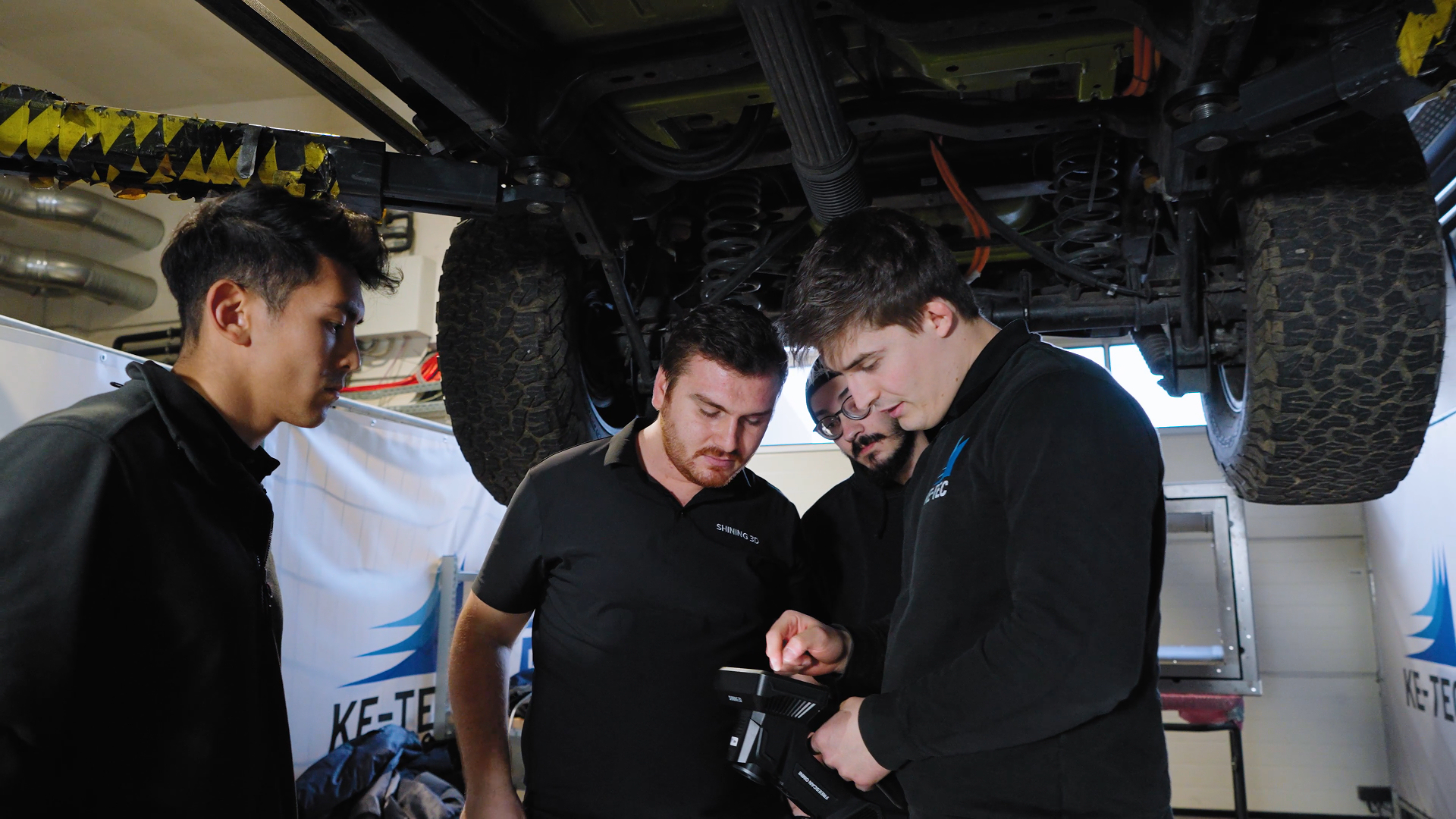
The limitation is coverage rather than competence. A CMM is tied to an environment-controlled laboratory, which makes it impractical for a multi-metre casting or a structure that is still mounted on an assembly line. Programming and fixturing also add time before the first data point is captured. In one documented aircraft component project, a CMM needed two to three days to programme before data collection could begin, and fixture design and manufacture could add up to three days more for the same part.
Checking fixtures carry a different kind of cost. A dedicated fixture typically takes one and a half to two months to design and build, and complex parts may require two separate fixtures. For thin or easily deformed stamping parts, contact probing also introduces a deformation risk during measurement itself.
What is missing is a method that records the whole surface, in the place where the part actually sits, without a part-specific fixture. That is the problem 3D inspection was developed to solve.
Why Whole-Field Data Moved Onto the Shop Floor
Scanning-based inspection is no longer a specialist laboratory tool. Grand View Research estimated the global 3D scanning market at USD 4.28 billion in 2024, while MarketsandMarkets valued the broader 3D metrology market — scanners, CMMs and sensors together — at USD 11.13 billion in the same year. The two figures are not directly comparable, because the market definitions differ. What both indicate is scale: optical measurement is now part of mainstream manufacturing quality management.
Within that market, quality control and inspection was the largest application segment in 2024, and automotive was the largest end-user industry. Regionally, North America held a 37% revenue share in 2024, while Asia Pacific is projected to be the fastest-growing region for 3D metrology at a CAGR of 8.0% through 2029.
Two technical developments explain the shift from laboratory to production floor. The first is the maturity of optical measurement standards. ISO 10360-13:2021 defines acceptance and reverification testing for optical 3D coordinate measuring systems, and VDI/VDE 2634 Part 3 covers multiple-view area-scanning systems. These standards give buyers a common basis on which to compare scanner performance instead of relying on specification claims alone. The second is workflow integration: inspection software now performs CAD comparison, GD&T evaluation and report generation in a single environment, and robotic cells can repeat the same inspection path without operator intervention.
How 3D Inspection Actually Works
3D inspection follows a fixed chain: acquire surface geometry, align it to a nominal reference, evaluate the difference, and document the result. Everything that distinguishes one system from another is a detail of how well each link in that chain is executed.
From surface capture to a comparable dataset
Structured light scanning projects a known pattern of light onto the object. The pattern deforms as it follows the shape of the surface, one or more cameras capture that deformation, and software compares the projected pattern with the captured pattern to calculate the 3D position of points on the surface. The system does not simply photograph the part; it reconstructs geometry from the way a known pattern changes across it.
Laser line scanning uses the same triangulation principle but projects lines rather than area patterns. Blue laser light sources are less sensitive to ambient light and surface reflectivity, which is why they are widely used on dark castings and machined alloys. Fixed blue LED structured-light systems project grating patterns and are used where dense surface data and very fine detail matter. Photogrammetry uses multiple 2D images taken from different angles to reconstruct a global reference frame, and is primarily used to control error accumulation when scanning large objects.
Photogrammetry's role deserves emphasis. When a part is several metres long, small errors in stitching individual scans accumulate, and the resulting volumetric error can exceed the tolerance being verified. Photogrammetry establishes a high-accuracy marker and coded-target framework around the part, and the scanner data is fitted into that framework. SHINING 3D's implementation, Video Photogrammetry (VPG), replaces sets of static images with continuous video capture, and on supported systems it removes the need for coded markers entirely.
Accuracy, precision, resolution and volumetric accuracy are not the same thing
Accuracy describes how closely a measured result matches the true physical dimension. If a 100.00 mm feature is measured as 100.02 mm, the error is 0.02 mm. Precision, also called repeatability, describes how consistently the same measurement is reproduced under unchanged conditions. Resolution describes the smallest detail the scanner can distinguish — and higher resolution does not automatically mean higher accuracy, because a scanner can capture very fine detail while still introducing dimensional error.
Volumetric accuracy describes accuracy across a larger scanning volume, and it is the number that matters when the part is big. Industrial scanners often express it as a formula such as 0.02 mm + 0.015 mm/m. For a two-metre-long object the resulting tolerance is 0.02 + (0.015 × 2) = 0.05 mm, meaning the maximum measurement error can increase to 0.05 mm over the full length. Cumulative error on large objects can be reduced with global markers and video photogrammetry, but it cannot be ignored when selecting a system.
Selecting a scanner on a single "accuracy" figure is therefore misleading. The tolerance the part actually needs, and the distance over which that tolerance must hold, determine which instrument class is appropriate.
Why industrial scanners and consumer scanners are not interchangeable
Consumer and hobbyist 3D scanners generate visually convincing models at low cost. They are genuinely useful for visualisation, basic design assistance and digital asset creation. What they do not provide is strict metrological traceability: the data cannot be used to sign off an engineering quality report. A metrology-grade scanner is specified and verified against recognised standards, calibrated against traceable artefacts, and supplied with acceptance documentation that a quality management system can file and audit.
The differences extend into daily operation. Industrial systems are built for material adaptability, for factory-floor environments, and for inspection software that performs GD&T evaluation rather than just mesh generation. They are also built for mobility: handheld and wireless configurations let the scanner travel to the part instead of the part travelling to a measuring room.
| Measurement approach | What it does well | Where it is limited | Typical role |
|---|---|---|---|
| Hand tools (calipers, gauges) | Fast checks of basic dimensions and simple geometry | Cannot capture the full 3D profile of freeform surfaces or complex curvature | Spot checks at the workstation |
| Coordinate measuring machine (CMM) | Reference accuracy on critical geometric features in regulated workflows | Tied to an environment-controlled lab; programming and fixtures add lead time; not practical for very large components | Reference measurement and audit |
| Consumer / hobbyist 3D scanner | Low-cost, visually convincing 3D models | Data lacks strict metrological traceability and cannot sign off an engineering quality report | Visualisation, basic design, digital assets |
| Metrology-grade 3D scanner | Full-field surface data, deviation colour maps and GD&T evaluation, on the shop floor or at the part | Requires a trained operator; highly reflective, glossy or translucent surfaces may need an ultra-thin scanning spray | Inspection of complex, freeform or large parts |
The 3D Inspection Workflow, Step by Step
A scanning-based inspection process is only as reliable as its weakest stage. The following sequence is the standard structure used in industrial quality control, and each stage has a specific failure mode worth controlling.
Step 1 — Define the inspection plan before touching the scanner
Decide what the data has to prove: the nominal CAD revision, the datum scheme, the tolerance bands, and the features that will be reported. Object size and tolerance then determine the scanner class. As a working rule, 0.005–0.02 mm suits functional safety parts and strict GD&T inspection; 0.02–0.05 mm suits assembly verification and structural analysis; 0.05–0.1 mm suits overall deformation analysis and surface deviation mapping on large or cosmetic parts.
Step 2 — Capture the data
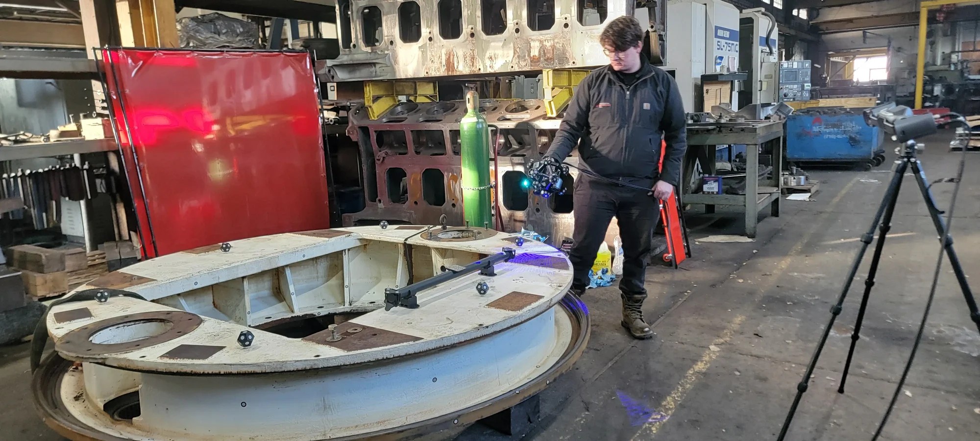
Handheld laser scanning captures freeform surfaces quickly. A dynamic tracking system maintains volumetric accuracy across a large workpiece and allows the scanner to move freely around it. Fixed structured-light systems are used where sub-0.01 mm detail is required on small and medium components.
Total inspection time is not the same as scan speed. It is the sum of setup, data capture and processing, and setup is frequently the largest term. On large objects, placing dozens or hundreds of reference markers can take longer than the scan itself. That is why marker-free tracking and video photogrammetry change the economics of large-part inspection rather than simply improving a specification.
Step 3 — Process, clean and align
Point cloud and mesh data are cleaned, merged and aligned to the datum scheme. Alignment determines the credibility of everything that follows: a technically perfect scan aligned to the wrong datums produces a confidently wrong report. Software that performs alignment and inspection in one environment reduces the chance of the datum scheme being re-created inconsistently between tools.
Step 4 — Compare against CAD and evaluate GD&T
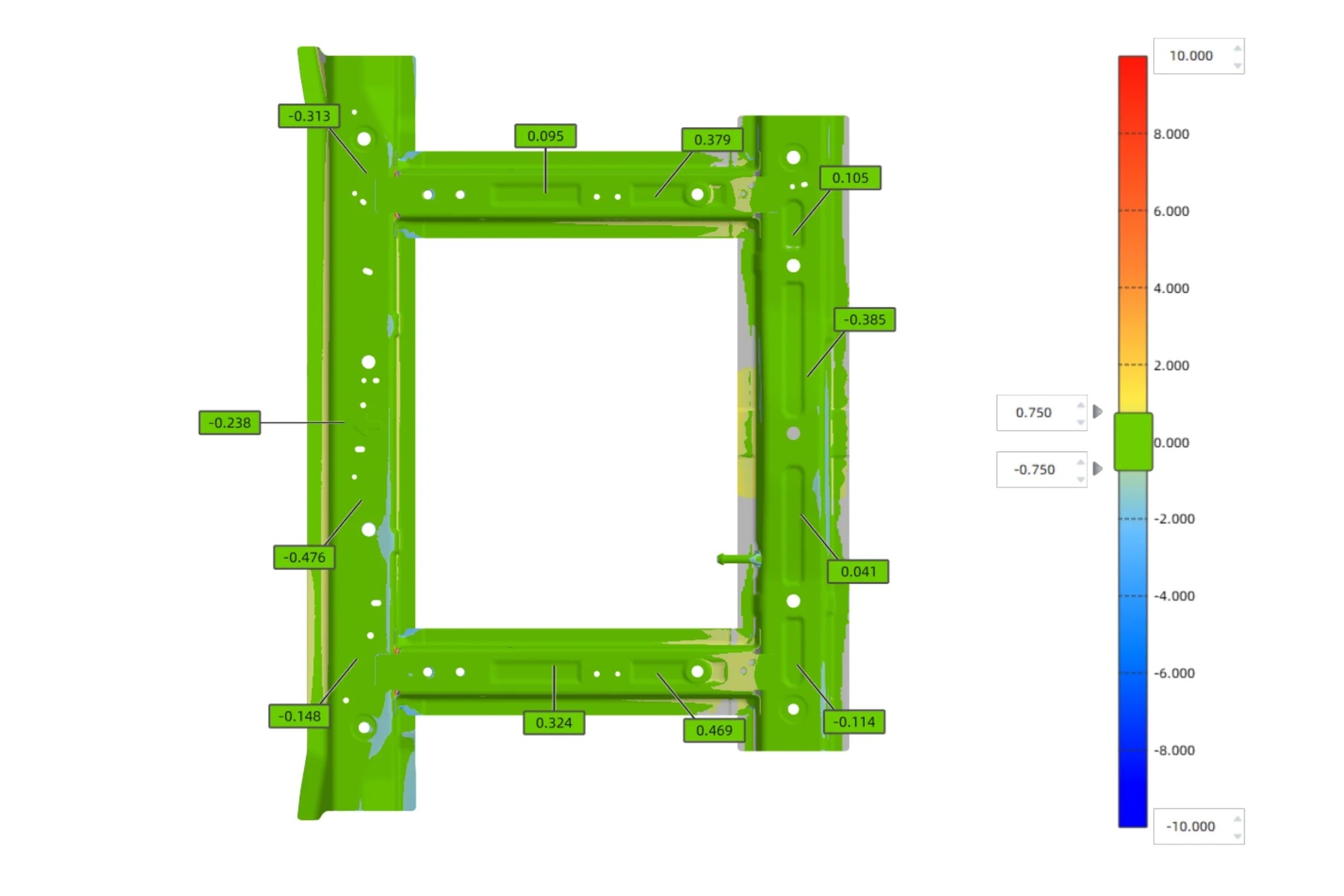
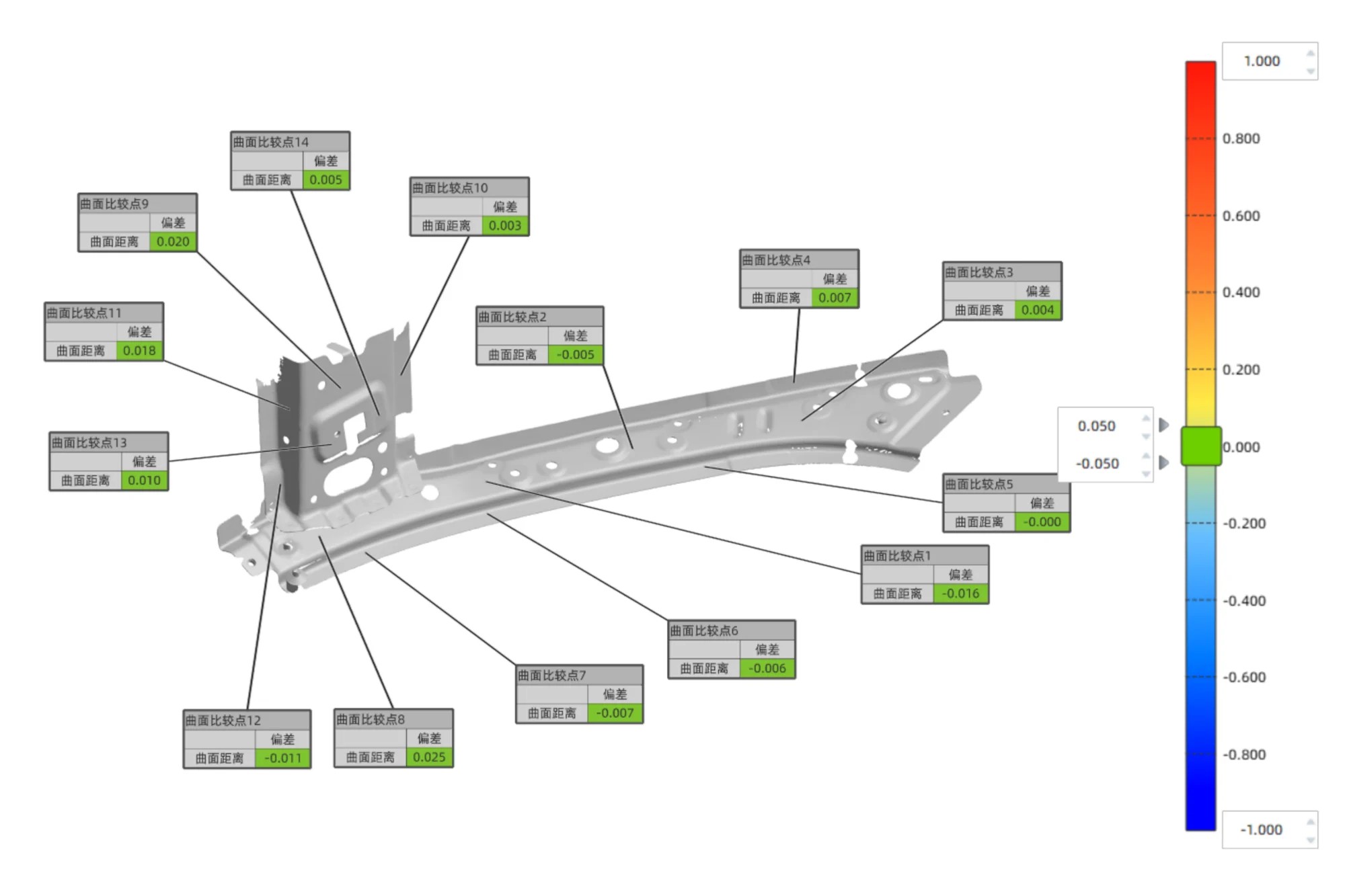
CAD comparison identifies dimensional variation, manufacturing deviation and potential quality issues. Colour deviation maps show where the surface sits outside nominal; dimensional and GD&T analysis converts that into position, form and profile results against the engineering standard. Cross-sections and feature measurements answer specific questions — wall thickness, hole position, flatness, cylindricity — without a second setup.
Step 5 — Report and archive
Inspection software organises measurement results, deviation information and analysis data into traceable reports. A report is only useful if it records the nominal revision, the datum scheme and the measurement conditions alongside the results, so that the conclusion can be reproduced later.
Step 6 — Feed the data back into the process
Repeated inspection of the same feature over time turns measurement into a trend. Tool wear, process drift and fixture degradation become visible before scrap is produced. This is where scanning-based inspection stops being a quality gate and starts being process information — and it is the reason digital inspection data is retained rather than filed and forgotten.
Where 3D Inspection Is Used
The applications below are documented installations. They illustrate the range of problems the same measurement logic solves, from a component measured in a few hours to a structure measured in a single day.
First article inspection and prototype verification
An aircraft component manufacturer in Thailand producing PMA parts used a handheld scanner for first article inspection. Compared with a CMM, which needed two to three days to programme before data collection could start, the scanner captured data in less than half a day. No jig or fixture was required, parts could be flipped or approached from any angle, and staff without previous 3D scanning experience reached working competence in about half a day. Blue laser handled the dark and reflective surfaces involved.
A comparable pattern appears in electronics. An EMI filter development and manufacturing facility in Hungary used a handheld scanner with inspection software for prototype inspection and measurement. Measurement time fell from roughly two weeks with outsourced partners, or three to four days with the internal measurement laboratory, to an average of two to three hours. Because the scanner captures complete surface data, checks remain possible even when a physical prototype is no longer available.
Stamping, sheet metal and fixture replacement
An automotive stamping parts manufacturer replaced dedicated checking fixtures with a general-purpose scanning system. A typical fixture takes one and a half to two months to design and build; removing that waiting period cut project time by at least one third. Custom fixtures can cost thousands of dollars per part, and complex parts may require two. Non-contact capture also removed the risk of deforming thin stamped parts during measurement. In a separate sheet metal application, non-contact measurement eliminated part-specific fixture replicas and allowed one system to cover multiple product types with simple supports.
Automated in-line inspection
An automotive OEM in Vietnam integrated a handheld 3D scanner with a robotic arm and inspection software to automate part measurement. With a designed fixture and an automated workflow, inspection time fell from approximately one hour to five minutes per part. Scanned data is compared with CAD models, deviation results are visualised on a real-time dashboard, and inspection records are stored in a database for traceability. The change also removed manual data entry and made repeat inspections consistent.
Large components and heavy machinery
A Western Australian steel manufacturer used a wireless tracking system to assess a 15-ton trommel screen shell returned from mineral processing plants. Scan data was compared against the original CAD model to identify deviations outside manufacturing tolerance and to determine exactly where refurbishment was required. Inspection tasks that previously took days took hours.
A machinery manufacturer used a handheld scanner with a photogrammetric system to inspect large structural components of giant mining trucks, achieving volumetric accuracy of 0.02 mm + 0.015 mm/m without moving the workpiece to a measuring room. In construction machinery manufacturing, the same class of equipment is used for fixture verification on the shop floor and for reverse engineering legacy components where CAD data is incomplete.
Energy, mold and marine applications
An EV battery developer and testing service provider in Germany scans battery housings after mechanical stress tests, using the scanner's onboard inspection module to align scan data with CAD immediately and visualise deformation on the spot. Because housings often exceed one metre, video photogrammetry is used to maintain volumetric accuracy of 0.02 + 0.015 mm/m across the whole structure.
A mold and custom equipment manufacturer in Thailand reduced inspection time from 30–45 minutes to 10–15 minutes per part, an overall inspection efficiency improvement of approximately 60%, using marker-free scanning with 0.023 mm accuracy. A propeller repair shop in Spain used a compact scanner for overhaul work in narrow spaces; the ability to assess propellers without disassembling components contributed to a 20% reduction in repair time.
Matching the Scanner Configuration to the Job
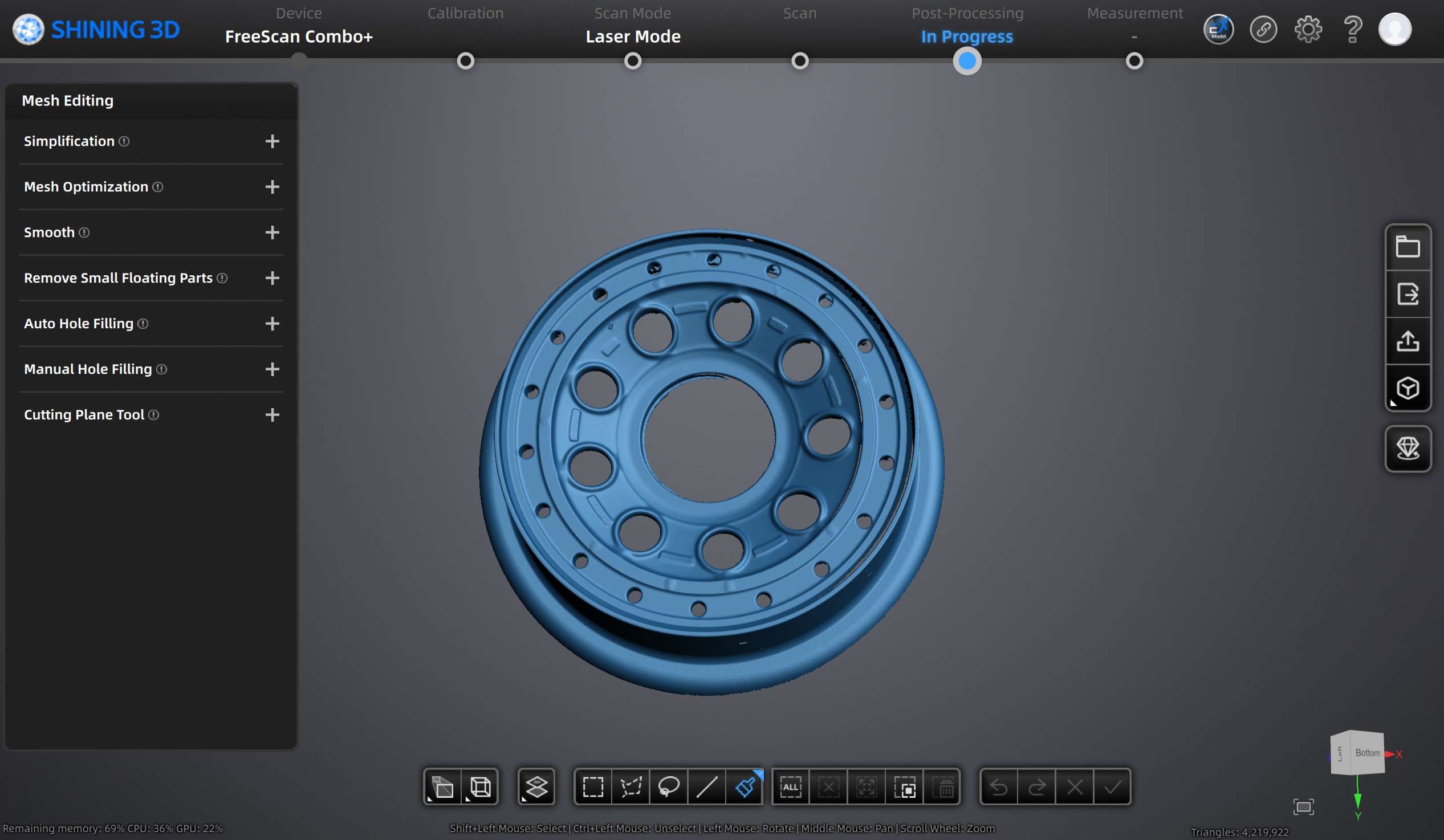
There is no single correct configuration. The right choice follows from object size, tolerance band, surface material and where the measurement has to happen. The table below summarises configurations within the SHINING 3D metrology range and the conditions each is designed for.
| System | Format | Certified accuracy | Capability notes |
|---|---|---|---|
| FreeScan Omni / FreeScan Omni Lite | Standalone wireless handheld metrology scanner | 0.02 mm | On-device, PTB-certified inspection without a laptop; VPG volumetric accuracy 0.02 + 0.015 mm/m; ≤1.1 kg with 5.5-inch touchscreen; scan speed up to 7,619,000 points/s; blue laser plus IR VCSEL |
| FreeScan Trak Nova Series | Wireless dynamic tracking and scanning system | 0.02 mm | Volumetric accuracy 0.062 mm over 12 m³; VPG 0.046 + 0.012 mm/m; flexible FOV up to 2600 × 2200 mm; 7,600,000 points/s; tracker can also operate as a standalone large-FOV handheld scanner |
| FreeScan Combo Series | Handheld hybrid light source scanner | 0.02 mm | Blue laser plus infrared VCSEL in a 620 g body; four scanning modes including marker-free IR; blue laser suited to dark and reflective surfaces |
| OptimScan Q12 / Q9 HD | Fixed blue LED structured-light inspection scanner | 0.004 mm (small range) | Four-camera system with dual scan range switching; Monocular-Stereo Fusion; manual, semi-automated or fully automated robot operation |
| AutoScan Inspec2 | Fully automated desktop inspection system | up to 0.01 mm | 140 × 90 × 80 mm scan range; AI supplementary scanning and path storage for batch inspection; multi-object mode for up to 8 parts |
All systems above are tested against VDI/VDE 2634 and ISO 10360 acceptance criteria in an ISO/IEC 17025 accredited accuracy laboratory. Configuration should be confirmed against the actual part, tolerance and environment rather than against the specification sheet alone.
Frequently Asked Questions
Can a 3D scanner provide an accuracy certificate traceable to ISO 10360 or VDI/VDE 2634?
Yes, for metrology-grade systems. The SHINING 3D Accuracy Laboratory is accredited to ISO/IEC 17025 by CNAS (China National Accreditation Service for Conformity Assessment), and because CNAS is a signatory to mutual recognition agreements such as ILAC MRA, its test reports and calibration certificates are recognised internationally. The laboratory performs accuracy tests and issues calibration certificates in compliance with VDI/VDE 2634 Part 2 and Part 3, and its testing protocols align with ISO 10360-12 and ISO 10360-13 for acceptance and reverification testing. All calibration and verification procedures are performed in that accredited laboratory, and scanners are calibrated using certified artefacts or calibration panels traceable to metrology standards.
Can 3D inspection handle dark, reflective or large parts without applying markers?
Material adaptability and marker strategies are separate questions, and both are answered by the light source and the tracking method. Blue laser light is less sensitive to ambient light and surface reflectivity, which makes it suitable for dark castings, machined alloys and similar industrial surfaces. Infrared VCSEL enables marker-free rapid scanning of feature-rich workpieces. On supported systems, patented Video Photogrammetry removes the need for coded markers while maintaining volumetric accuracy — for example 0.02 + 0.015 mm/m on FreeScan Omni and 0.046 + 0.012 mm/m on FreeScan Trak Nova Series. For very large surfaces, reference markers may still be recommended to secure the best volumetric result.
Can a 3D scanner be used for first article inspection, and how does it compare with CMM setup?
Yes. FAI requires verification of the complete geometry against the nominal model, which is where full-field capture has an advantage over key-point checking. The practical difference is preparation time. In a documented aircraft component project, a CMM needed two to three days to programme before data could be collected, and fixture design and manufacture could add up to three days; the 3D scanner captured data in less than half a day, required no jig or fixture, and allowed the part to be flipped or scanned from any angle. Operators without prior 3D scanning experience became productive in about half a day. Scanning is not a replacement for CMM reference measurement on critical features, but it makes complete geometric evidence available early in a project.
What are the typical purchase terms for an industrial 3D scanner?
For SHINING 3D systems, the minimum order quantity is 1 unit, and both OBM (Original Brand Manufacturing) and ODM (Original Design Manufacturing) production services are offered, with logo and automation solution customisation available. Typical production lead time is 30–45 days. Delivery terms include FOB, CFR, DAP and FCA. Payment terms are 100% advance payment or instalment payment. Acceptance criteria are delivery inspection or post-installation acceptance. Every unit is subject to 100% test before shipment, and after-sales support is available remotely and on site.
How can a buyer validate a scanner on their own parts before committing?
The most reliable validation is to scan parts you already understand: one conforming part with known dimensions and one part with a known deviation. Check repeatability on the same feature, confirm how the system handles your actual surface finish and material, verify whether markers are needed at your part size, and run the GD&T output through the inspection software you intend to use in production. If the part is large, confirm volumetric performance over the full length rather than at a single position. Scan evaluations and quotations can be requested through shining3d.com or by writing to marketing@shining3d.com.
Conclusion
3D inspection is best understood as a change in the unit of evidence. Instead of a set of points that a fixture happened to define, the quality team works with the complete surface, aligned to the nominal model, evaluated against the tolerance scheme and documented in a traceable report. That is what allows a casting, a stamped panel, a battery housing or a two-metre structural component to be assessed in hours rather than days — and it is what makes the data reusable for trend analysis instead of being archived and forgotten.
The capability questions that decide whether a system is suitable are narrow and answerable: the tolerance band and the distance over which it must hold, the size and material of the part, whether markers are practical, where the measurement has to take place, and what documentation the quality system requires. A metrology-grade scanner that answers those questions is a working instrument. A low-cost scanner that produces attractive models but no traceable measurement is a different product for a different job.
Next Step
If you are evaluating scanning-based quality control, the quickest way to a decision is to test the workflow on your own components. SHINING 3D can support a scan evaluation, a technical quotation and a distributor or OEM discussion depending on your position in the supply chain.
Product catalogue and technical overview: SHINING 3D 3D Digitizing Introduction (PDF)
Website: www.shining3d.com
Email: marketing@shining3d.com | Tel: +86 571 8299 9050

Have Questions or Need More Details?
Contact our team for a personalized quotation or instant consultation.
Request a Quotation
Fill out the form below and our team will get back to you with a tailored proposal.
WhatsApp Direct Chat
Prefer to chat in real-time? Message us on WhatsApp for instant assistance & quick answers.
- Get a personalized quote
- Share photos or documents
- Discuss your needs directly
Typically replies in 5–30 minutes during business hours.