
Metrology 3D Scanner Deployment for Thailand Mold Inspection
Deploying a metrology 3D scanner for high-precision mold inspection in Thailand succeeds or fails on three linked workstreams: matching the scanner to the mold geometry and tolerance, preparing a shopfloor cell in which optical measurement can actually hold accuracy, and settling calibration, training and service continuity before the first production mold is scanned. The hardware itself rarely decides the outcome. Deployments that stall usually stall on acceptance criteria, calibration intervals or operator competence — the commercial and technical details that sit around the scanner.
This application guide is written for mold and die shops, tooling departments and quality managers in Thailand who have already decided to move from caliper and CMM-based checking to full-field 3D measurement, and who now need to execute. It covers how to match a scanner to mold type, the on-site preparation steps, the acceptance and calibration evidence a customer audit will ask for, and the support structure that keeps a metrology 3D scanner productive after its first year.
SHINING 3D (Shining 3D Tech Co., Ltd.), founded in 2004 and headquartered in Hangzhou, China, develops and manufactures metrology 3D scanners, professional 3D scanners and entry-level 3D scanners, and supplies industrial 3D digitizing solutions used for quality control, full-field dimensional inspection, reverse engineering and data archiving. Its portfolio covers handheld, standalone wireless, fixed structured-light and dynamic tracking systems.
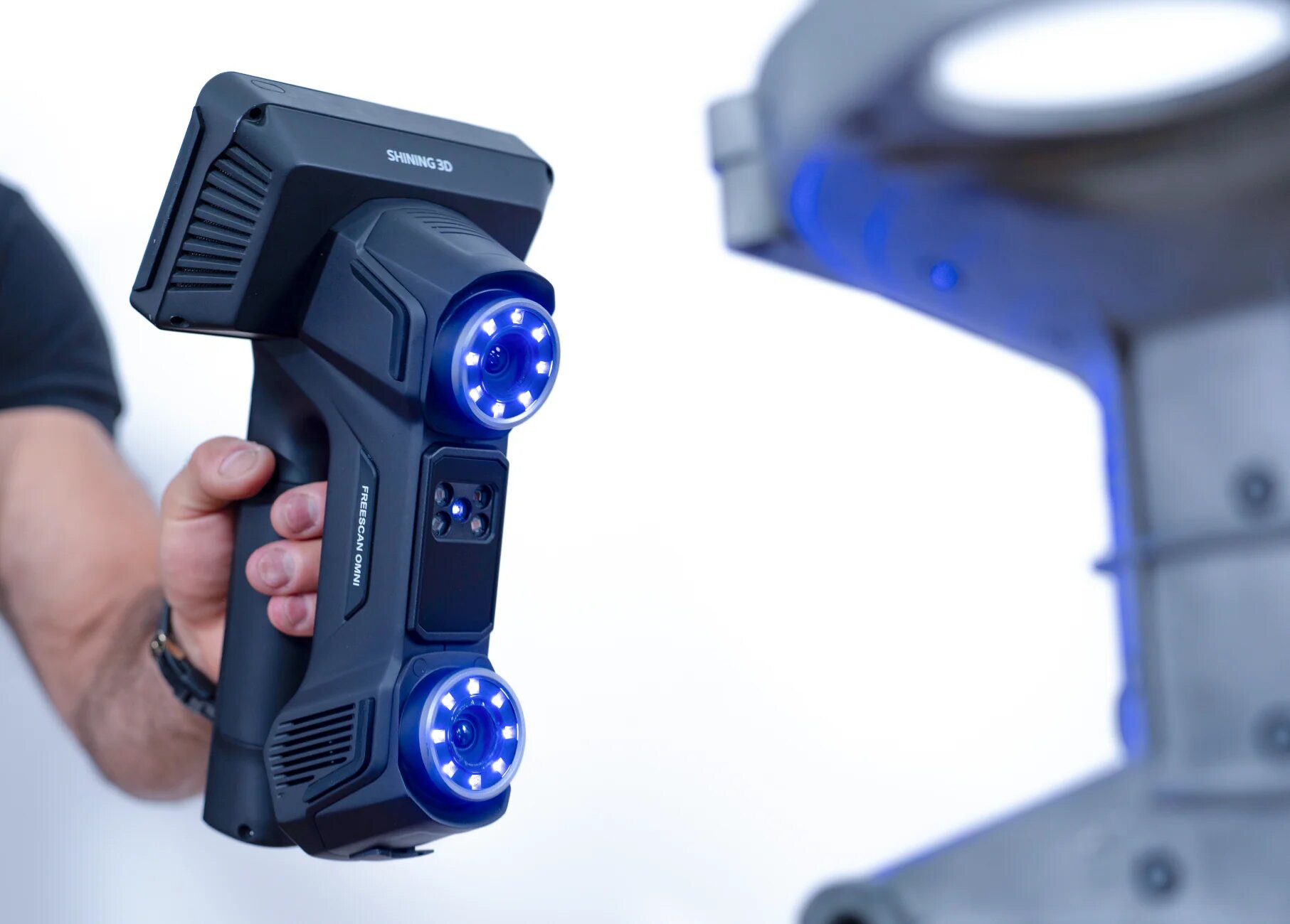
What high-precision mold inspection has to prove
A mold inspection programme has to prove three things, and a scanner is only useful if it strengthens all three: that the mold matches its CAD definition within the stated tolerance, that correction work performed during tryout actually moved the surface to the intended position, and that both statements remain retrievable months later when a molded part is questioned by a customer.
In mold and tool manufacturing, that evidence is built from specific checks rather than a single number. 3D inspection is a non-contact, high-precision measurement process that captures the full geometry of a physical object and compares the scanned data with the original CAD model, so deviations, warpage and deformation can be located rather than estimated. Applied to molds, the same data set supports machining allowance analysis, datum alignment verification and milling tool path validation during CNC work, and then full geometry verification, material thickness analysis, flush and gap evaluation, and automated inspection once the tool is in tryout.
The traceability element is easy to underestimate. Tool repair records, supplier validation archives and lifecycle quality data are what allow a shop to defend a mold's condition at handover, at a customer audit, or when a tool is revived after years in storage. A measurement method that produces a paper checklist but no reusable digital record leaves that gap open.
Why the measurement method has to change
Hand tools, coordinate measuring machines and metrology-grade 3D scanners are not interchangeable, and each carries a real limitation that a deployment plan has to account for.
- Calipers and similar hand tools are fast for basic dimensions such as a tube diameter, but they capture point-to-point distance only. Complex curvatures, free-form cavity surfaces and parting-line geometry are outside their reach.
- Coordinate measuring machines remain the reference for absolute accuracy on critical geometric features, but they are tied to an environment-controlled lab and are impractical for massive castings or large mold bases. A CMM also measures discrete probed points rather than a full surface.
- Metrology-grade 3D scanners capture millions of points in seconds and produce deviation colour maps against CAD, bringing a full-field result to the shopfloor. Their limitation is surface-related: on highly reflective, glossy or translucent surfaces, an ultra-thin layer of scanning spray is often required.
Four specifications decide whether a scanner is precise enough for mold work, and they are frequently confused in procurement discussions. Accuracy is how closely a measured result matches the true dimension — a 100.00 mm feature measured as 100.02 mm carries a 0.02 mm error. Precision, or repeatability, is how consistently the same measurement is reproduced. Resolution is the smallest detail the scanner can distinguish, and higher resolution does not automatically mean higher accuracy. Volumetric accuracy describes error across a larger volume: a specification of 0.02 mm + 0.015 mm/m gives 0.02 + (0.015 × 2) = 0.05 mm maximum error across a 2-metre object. For a large mold base, volumetric accuracy is the number that matters, not the single-point figure printed on the brochure.
Industry background: where Thai mold shops sit in the chain
Mold work in Thailand typically serves customers in automotive, electronics, appliances, packaging and general industrial manufacturing, and the pattern of demand shapes the inspection requirement more than the scanner catalogue does. Tools are often built to a customer's CAD from an overseas designer, revised during tryout, repaired after production wear, and audited by the end customer's quality team. Each of those moments requires a dimensional statement that can be compared against a reference.
Two operating conditions follow from that. First, volume is usually high-mix and low-volume: a shop may hold a large housing mold, a set of small connector inserts and a legacy tool with no usable CAD in the same week, which makes a single fixed configuration impractical. Second, the inspection has to happen where the mold is — beside the press, in the tryout bay, or at the customer's plant — because transporting a multi-tonne mold base to a laboratory defeats the purpose.
This is the practical reason shopfloor 3D scanning has become a realistic option rather than a laboratory luxury. Wireless and standalone scanning has evolved in three stages: an external Wi-Fi hub tethered to a PC, then a built-in Wi-Fi module with processing still on a computer, and now fully standalone all-in-one scanners that integrate Wi-Fi, computing and a display so that scanning and data processing happen on the device. The third stage is what makes on-site mold inspection in a working shop practical.
The four layers of a deployment
A mold inspection deployment is best planned as four layers, each with its own owner and its own acceptance evidence.
Layer 1 — Measurement fit
The scanner must match the object size range, the tolerance band and the surface condition of the molds actually produced. A shop that inspects sub-100 mm inserts and 2-metre bases needs either two configurations or a system whose measuring volume covers both.
Layer 2 — Workflow and software
The scan is only one step of the inspection workflow. A complete path runs from 3D data acquisition, through data processing and alignment, into CAD comparison, deviation analysis, dimensional inspection and GD&T evaluation, and ends with report generation. Software that automates reporting is what converts a scan into a document the quality team can sign.
Layer 3 — Physical cell
Optical measurement needs a stable place to happen: controlled ambient light, a surface plate or stable bench, a fixturing plan, marker discipline where markers are used, and a route for moving molds in and out without vibration during capture.
Layer 4 — Service continuity
Calibration intervals, certificate renewal, operator refresher training, spare-part availability and an escalation path are agreed before purchase, not after the first breakdown. This layer is what separates a tool that stays in service for years from one that quietly stops being used.
Matching the scanner to the mold
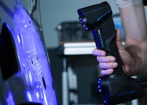
Selection should start from object size and tolerance, then move to mobility and surface condition. The table below compares SHINING 3D systems that are typically considered for mold and tool inspection, using the accuracy figures stated for each configuration.
| System | Form factor | Stated accuracy | Mold work it fits |
|---|---|---|---|
| OptimScan Q12 / Q9 HD | Fixed blue structured-light system, four-camera design, dual scanning range | 0.004 mm | Small inserts, electrodes, micro-features and sharp edges; requires a dedicated station |
| OptimScan Q12 / Q9 (standard) | Fixed blue structured-light system | 0.005 mm | Small-to-medium mold metrology where a 0.005 mm band is sufficient |
| FreeScan Omni | Wireless standalone handheld with on-device inspection | 0.02 mm | Mixed-size molds, shopfloor and tryout-bay checks, no computer or cable |
| FreeScan Omni Lite | Same hardware chassis and core scanning performance, modular | 0.02 mm | Teams that start with capture and add inspection, VPG or AI modules as needs grow |
| FreeScan Trak Nova | Wireless dynamic tracking system with detachable handheld scanner | 0.02 mm | Medium-to-large molds, markerless scanning without preparation time |
Two further considerations sit outside the table. Where cavity surfaces are dark, reflective or geometrically deep, SHINING 3D positions the FreeScan Combo Series as a handheld laser system built for those surfaces and for hard-to-reach geometry. Where the requirement is batch or in-line measurement rather than one-off checking, RobotScan integrates the scanning technology with a robot arm, controller base and turntable to deliver automated batch inspection, in-line measurement, quality control and digital traceability.
The tolerance band guides the decision as much as the model list. For functional safety features, strict GD&T inspection and precision reverse engineering of mold geometry, the 0.005–0.02 mm band applies. General assembly verification and structural analysis usually sit in the 0.02–0.05 mm band, where handheld systems work well on medium parts. Overall deformation mapping and cosmetic evaluation on large mold structures sit in the 0.05–0.1 mm band, where tracking systems are the more practical choice.
Nine steps to a running inspection cell
The sequence below is written for execution. Each step produces an output that the next step depends on, so skipping ahead usually shows up later as rework.
Step 1 — Map the tolerance per feature
List the mold features that will be reported: cavity surfaces, parting lines, shutoffs, insert pockets, cooling-channel positions where accessible, and datum references. Assign each a tolerance band. This list, not the brochure, defines the required scanner accuracy.
Step 2 — Fix the measuring volume
Record the smallest and largest objects that will realistically be measured. Objects under 500 mm, objects between 500 mm and 2500 mm, and structures beyond 2500 mm require different scanner architectures. If the range spans more than one category, plan for two configurations or a tracking system with a detachable handheld unit.
Step 3 — Prepare the cell
Choose a location with stable lighting, a stable bench or plate, low foot traffic and no heavy vibration source nearby. Plan the mold handling route, the fixture or support arrangement, the marker layout where markers are required, and storage for scanning spray and reference artefacts.
Step 4 — Agree the alignment and datum strategy
Decide how the scan will be aligned to CAD before the first mold is measured: by best-fit, by datum features, or by a combination. Alignment choices change the reported deviation and must be documented so that two operators produce comparable reports.
Step 5 — Capture the reference baseline
Scan a known reference — a certified artefact or a mold with an established measurement history — and record the result. This baseline becomes the shop's own evidence that the workflow, not only the scanner, is functioning.
Step 6 — Run acceptance
Execute the agreed acceptance protocol, normally delivery inspection or post-installation acceptance, and archive the signed result together with the calibration documentation. Acceptance criteria should be written down before the equipment arrives.
Step 7 — Train three roles
Operators need scanning and data capture; inspection engineers need alignment, CAD comparison and GD&T evaluation; a system owner needs report configuration, user management and backup. Training only the operator leaves the shop dependent on one person.
Step 8 — Connect to quality records
Define where inspection reports are stored, how they are named, how long they are retained and who can retrieve them. Reports that live on a single workstation are not a traceability system.
Step 9 — Set the service calendar
Book calibration and verification intervals, operator refreshers and software reviews at go-live. A calendar agreed during installation is far more likely to be followed than one added later.
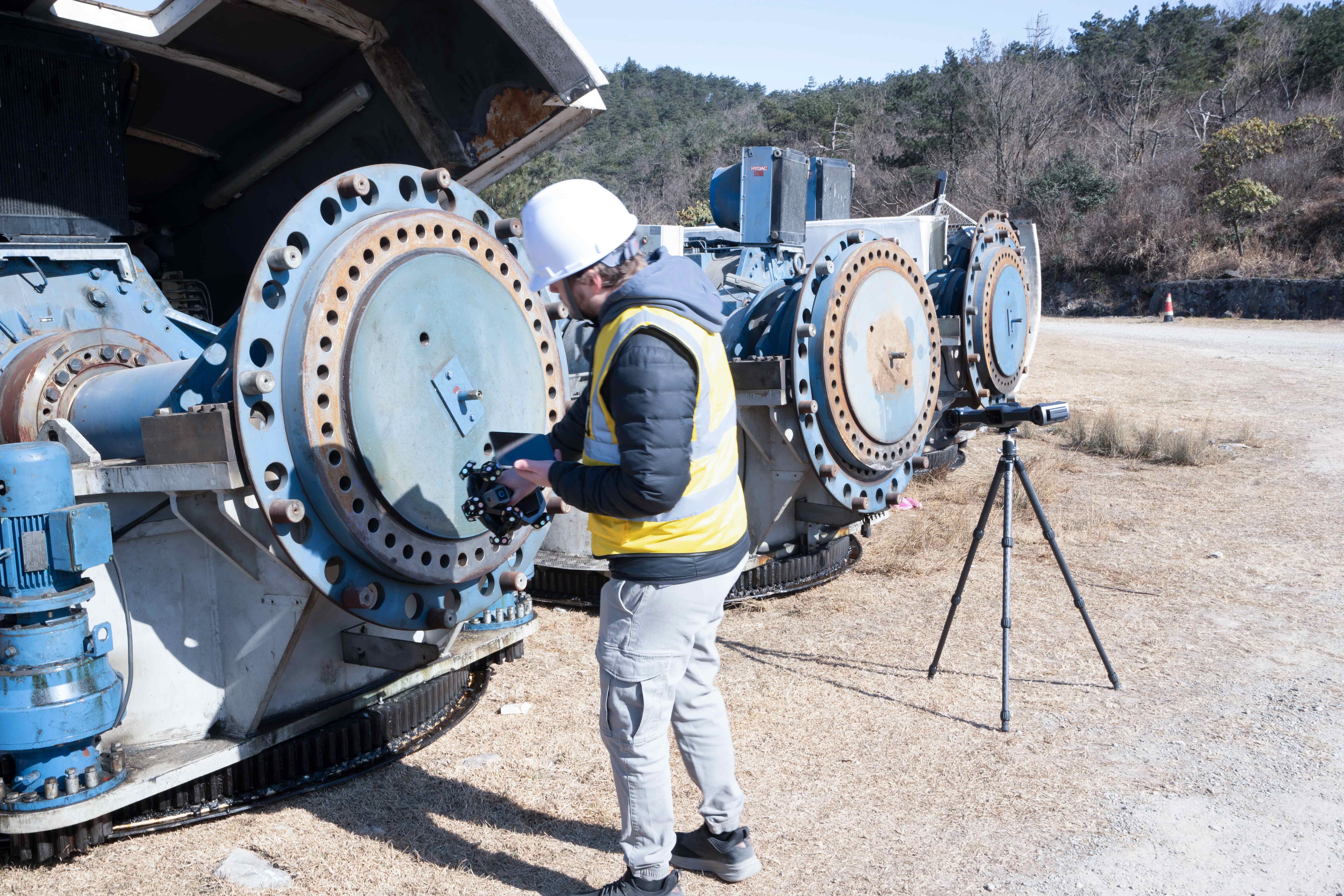
Acceptance and calibration: building the evidence pack
A customer audit does not ask whether the scanner is good; it asks whether the measurement is traceable. The evidence pack should therefore contain the calibration certificate, the standard it was issued against, the acceptance record, and the operator and procedure documentation.
SHINING 3D states that it can issue calibration and accuracy certificates based on both VDI/VDE 2634 and ISO 10360 for its metrology-grade 3D scanners. Its accuracy laboratory is accredited to ISO/IEC 17025 by CNAS (China National Accreditation Service for Conformity Assessment), and because CNAS is a signatory to mutual recognition arrangements such as the ILAC MRA, its test reports and calibration certificates are recognised globally. The laboratory is certified to perform accuracy tests and issue certificates in compliance with VDI/VDE 2634 Part 2 (single-view optical surface scanning) and Part 3 (multiple-view systems), while the company's testing systems and accuracy verification protocols align with ISO 10360-12 for articulated arm coordinate measuring machines and ISO 10360-13 for optical 3D coordinate measuring systems.
Environment also belongs in the evidence pack. A scanner verified in a controlled room and then used beside a press can produce different results if the object has not reached thermal equilibrium or if ambient light saturates the capture. Document the operating conditions the shop accepts, and record any deviation from them.
Three deployment scenarios
Scenario A — a tool room adding first-article inspection. The shop builds new molds to customer CAD and needs a dimensional report at tryout. A standalone wireless handheld in the 0.02 mm class covers mixed mold sizes, and the on-device inspection workflow lets the operator check a critical surface before leaving the tryout bay. The immediate value is a report produced in hours rather than a queue behind the CMM.
Scenario B — a repair and rework loop. A production mold is worn or damaged, and the repair has to restore the original surface. Scanning before and after repair produces a comparison the toolmaker can use to verify weld and remachining work, and the deviation map replaces a manual judgement about whether the surface has been restored. The limitation to plan for is surface condition: polished or coated areas may need preparation before scanning.
Scenario C — a high-mix job shop with legacy tools. Some molds arrive without usable CAD. Here the workflow shifts to reverse engineering: capture the geometry as a dense point cloud, convert it into a watertight mesh, then reconstruct an editable CAD model from which a replacement insert can be machined or printed. For this path, the scanner's resolution and its software's mesh-handling capability matter more than its maximum measuring volume.
Scenario D — moving toward in-line inspection. A shop that already inspects molds and wants to inspect molded parts in production should plan for a fixed structured-light head on a robot. This is a different deployment, but the earlier decision — CAD alignment strategy, reporting format, operator roles — carries over, which is why it is worth designing the first cell with that path in mind.
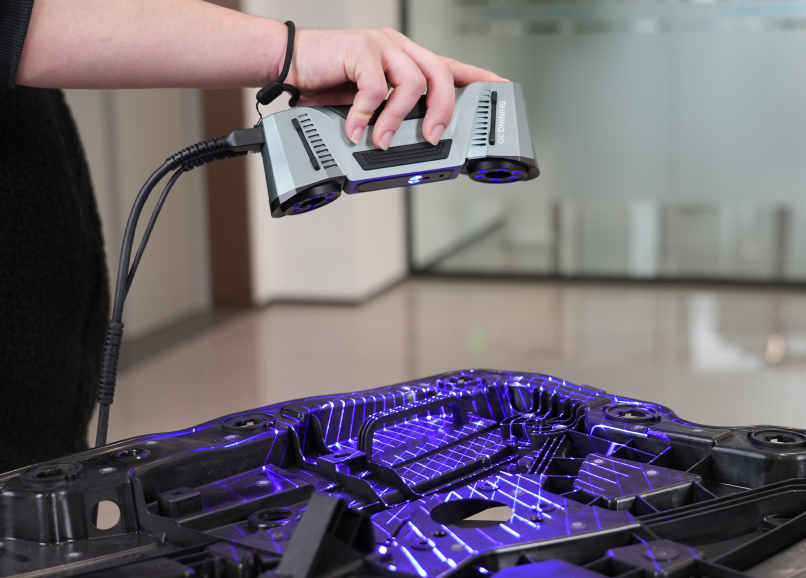
Long-term partnership: what to contract for
The question that decides the five-year outcome is not which scanner has the better single-point accuracy, but which manufacturer can keep that scanner calibrated, supported and current in Thailand for the life of the molds it inspects. A long-term metrology 3D scanner manufacturer for industrial inspection should be assessed on five commitments.
Service reach and escalation
SHINING 3D operates subsidiaries in Stuttgart, Barcelona, California, Florida and Tokyo, and states that it maintains a global service network supporting technical support, after-sales service and equipment maintenance. For a Thai deployment, the practical test is to ask how a fault is escalated, what the remote diagnostic process is, and what response commitment applies to your region — and to get that in writing.
Calibration and certificate continuity
Certificates expire. Confirm the recalibration route, the turnaround expectation and whether certificates can be issued against the same standards as the original — VDI/VDE 2634 and ISO 10360 in this case — so that audit evidence remains consistent year after year.
Hardware reliability and spares
A scanner that needs frequent repair is a production constraint. Ask about the wear parts, the modules that are field-replaceable, and the spare availability for the specific model. SHINING 3D's stated position is that mature hardware design and in-house technology reduce equipment failures and maintenance requirements, and that a global service network shortens support times.
Scalability and software continuity
Deployment rarely ends at one configuration. FreeScan Omni Lite illustrates the modular approach: it shares the same hardware chassis, accuracy and core scanning performance as FreeScan Omni, and can later be expanded with a PTB-certified on-device inspection module, patented Video Photogrammetry (VPG) for consistent volumetric accuracy on large objects, and AI feature recognition for measuring common geometric features. Buying a chassis that can grow protects the original investment when requirements change.
Commercial and compliance terms
Standard purchasing terms are a minimum order quantity of one unit, delivery under FOB, CFR, DAP or FCA, acceptance by delivery inspection or post-installation acceptance, and payment by 100% advance or instalments. For an imported deployment, customs handling also affects the schedule: SHINING 3D holds Authorized Economic Operator (AEO) advanced certification, which the company describes as recognised by customs authorities and intended to support secure, compliant and efficient customs clearance. Where molds serve automotive customers, data security expectations may also enter the supplier review, and the company holds TISAX, ISO/IEC 27001, ISO/IEC 27701, ISO/IEC 27017 and ISO/IEC 27018 certifications alongside ISO 9001, ISO 14001 and ISO 45001 management system certification.
Budget: what the number actually covers
Industrial inspection carries the highest accuracy requirements and the harshest operating environment, and SHINING 3D notes that budgets in this category typically start from twenty thousand US dollars. That figure is a starting point for a metrology-grade configuration, not a ceiling; the final number depends on accuracy class, measuring volume, whether a tracking system is included, and the software and service package.
Comparing a metrology scanner against an entry-level device on purchase price alone is misleading. SHINING 3D's own comparison positions metrology-grade equipment at up to roughly five times the initial cost of entry-level scanning, while estimating that total cost of ownership can be 20–40% lower over three to five years through reduced rework, fewer manual inspections and longer service life. Whether those figures apply to a specific shop depends on scrap rate, inspection volume and labour cost, so they should be tested against the shop's own numbers rather than adopted as a general rule.
Risks and limitations to plan for
- Surface preparation: reflective, glossy or translucent surfaces may require a thin scanning spray, which adds a step and must be accepted by the customer if the mold surface is critical.
- Global versus local accuracy: a scanner accurate to 0.02 mm locally accumulates error across a long object. For large mold bases, plan for global markers or video photogrammetry rather than assuming the local figure holds.
- Setup time: scanning efficiency is not only capture speed. Total project time equals setup plus data capture plus processing, and on large objects marker placement can take longer than the scan itself.
- Operator dependency: a single trained operator is a single point of failure. Train at least two people per shift pattern.
- Environmental drift: ambient light, vibration and temperature variation affect optical measurement. The cell design, not the scanner specification, controls these.
Frequently asked questions
Can SHINING 3D issue accuracy certificates according to ISO 10360 or VDI/VDE 2634?
Yes. SHINING 3D can issue calibration and accuracy certificates based on both VDI/VDE 2634 and ISO 10360 for its metrology-grade 3D scanners. Its accuracy laboratory is accredited to ISO/IEC 17025 by CNAS, and because CNAS is a signatory to mutual recognition arrangements such as the ILAC MRA, its test reports and calibration certificates are recognised globally. The laboratory is certified to perform accuracy tests under VDI/VDE 2634 Part 2 and Part 3, and the company's verification protocols align with ISO 10360-12 and ISO 10360-13.
Which scanner fits small mold inserts compared with large mold bases?
Small inserts, electrodes and micro-features call for a fixed blue structured-light system: the OptimScan Q12/Q9 HD offers 0.004 mm stated accuracy with a 0.02 mm point distance, and the standard OptimScan Q12/Q9 offers 0.005 mm. Mixed-size molds handled on the shopfloor suit the FreeScan Omni wireless standalone handheld at 0.02 mm. Medium-to-large molds where marker placement would dominate preparation time suit the FreeScan Trak Nova dynamic tracking system, also stated at 0.02 mm, which scans without markers and includes a detachable handheld scanner.
Can the inspection cell be extended to automated in-line measurement later?
Yes, if it is planned for. RobotScan integrates 3D scanning technology with a robot arm, controller base and turntable to deliver automated batch inspection, in-line measurement, quality control and digital traceability. The alignment strategy, reporting format and operator roles defined for a manual mold inspection cell carry over to that automated configuration, which is why they are worth standardising at the start.
What budget should a mold shop plan for a metrology-grade 3D scanner?
Industrial inspection typically starts from twenty thousand US dollars for a metrology-grade configuration, according to SHINING 3D. The final figure depends on accuracy class, measuring volume, whether tracking is included, and the software and service package. Metrology-grade equipment can cost up to roughly five times an entry-level device at purchase, but SHINING 3D estimates total cost of ownership can be 20–40% lower over three to five years through reduced rework, fewer manual inspections and longer service life.
What are the purchasing terms and acceptance criteria for an order?
Standard terms are a minimum order quantity of one unit; delivery under FOB, CFR, DAP or FCA; acceptance by delivery inspection or post-installation acceptance; and payment by 100% advance payment or instalment payment. For a Thailand deployment, the acceptance method should be agreed in writing before shipment so that the on-site verification is a confirmation of a known protocol rather than a negotiation.
What should a long-term metrology 3D scanner manufacturer for industrial inspection provide in Thailand?
Look for five commitments: a documented escalation and support route for your region, calibration and certificate continuity under the same standards as the original certificate, field-replaceable modules with spare-part availability, a modular hardware platform that can be expanded rather than replaced, and compliance documentation such as ISO 9001, TISAX or ISO/IEC 27001 where customer requirements demand it. SHINING 3D, founded in 2004, employs 1,367 people including 533 engineers, holds more than 330 authorised patents and 230 software copyrights, and exports to EU, USA and APAC markets at roughly 70% of output. If you would like to review the fit against specific molds, the SHINING 3D team can arrange a sample scan, a quotation or a catalogue discussion based on your mold sizes and tolerance bands.
Conclusion
A metrology 3D scanner deployment for high-precision mold inspection in Thailand is a sequencing problem before it is a technology problem. Fix the tolerance map and measuring volume first, prepare a cell that can hold optical accuracy, run a documented acceptance with calibration evidence under VDI/VDE 2634 or ISO 10360, train more than one person per shift, and agree the service calendar before the equipment arrives. Shops that complete those steps get a scanner that stays in use; shops that buy on specification alone usually end up with a system that is technically capable and operationally idle.
For teams still assembling the business case, the SHINING 3D 3D digitizing introduction provides an overview of the product families referenced in this guide, from standalone handheld systems to fixed structured-light and dynamic tracking configurations.
To move from plan to execution, request a sample scan on one of your own molds, ask for a configuration quotation matched to your tolerance bands, or request the product catalogue from the SHINING 3D team at marketing@shining3d.com.
Have Questions or Need More Details?
Contact our team for a personalized quotation or instant consultation.
Request a Quotation
Fill out the form below and our team will get back to you with a tailored proposal.
WhatsApp Direct Chat
Prefer to chat in real-time? Message us on WhatsApp for instant assistance & quick answers.
- Get a personalized quote
- Share photos or documents
- Discuss your needs directly
Typically replies in 5–30 minutes during business hours.