
3D Scanner for Quality Control: Inline Inspection Guide for Smart Manufacturing
A 3D scanner for quality control earns its place in smart manufacturing when it becomes an inline inspection cell, not a standalone scanner used in a lab. In practice, that means a repeatable sequence: the part is presented to the scanner, full-field 3D data is captured, the mesh is aligned to CAD, and a deviation or GD&T result is returned to the line. SHINING 3D Tech Co., Ltd., a Hangzhou-based 3D vision company founded in 2004, builds the RobotScan Series around that sequence. It combines a high-accuracy 3D scanner, an industrial robot or collaborative robot, a turntable, fixtures, and control and inspection software. For parts within its published cell envelope, it offers a practical path from discrete CMM probing to automated full-field inspection.
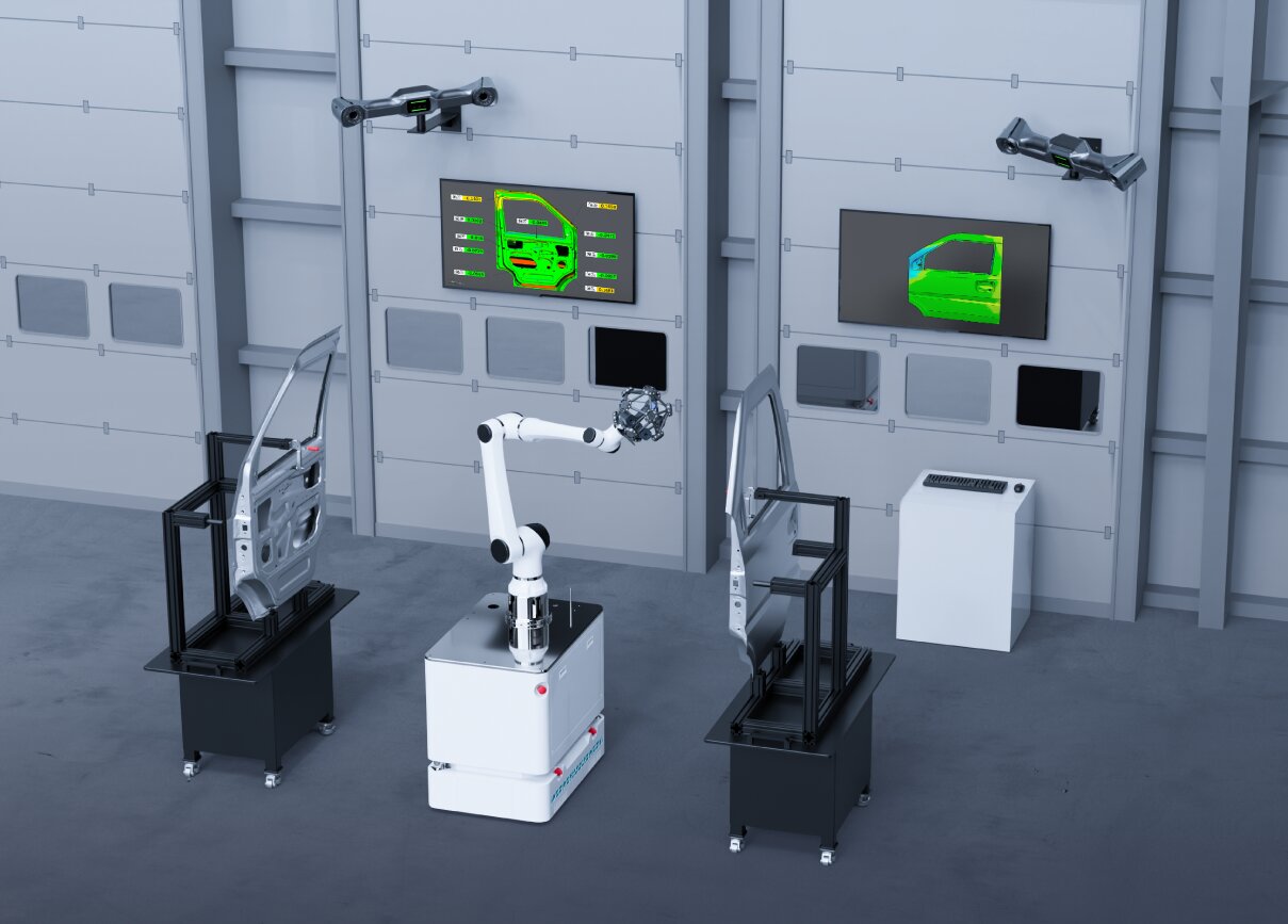
RobotScan Series can be configured as an automated 3D inspection cell for smart manufacturing quality control.
Problem Definition: The Bottleneck Is the Inspection Cell, Not the Scanner
The constraint in most quality-control workflows is rarely the scanner's point rate. The real constraint is the inspection system's ability to present the part, capture the right surfaces, align data to CAD, and release a decision without a lab queue. A coordinate measuring machine (CMM) touches discrete points along a programmed path. It is accurate and traceable, but it can require part-specific fixtures and programming.
The setup burden is well documented. In an aircraft PMA component inspection case published by SHINING 3D, the user reported that a CMM would take two to three days to set up the program for the same part, while a 3D scanner captured data in less than half a day. The same case noted that CMM fixtures could take up to three days to design and manufacture. The 3D scanner did not require a jig or fixture for that application. For inline inspection, that difference in preparation time is often the real bottleneck.
An inline cell also changes the quality question. Instead of asking whether a few key points are in tolerance, the team can inspect the full surface, compare the entire mesh to CAD, and see where the process is drifting between those points. That is the value of full-field 3D data capture. It does not make CMM obsolete. It gives production a faster feedback loop for the surfaces, freeform geometry, holes, slots, and deviation patterns that are hard to capture with discrete probing alone.
Industry Background: Quality Control Is Now the Main 3D Scanning Application
3D scanning is no longer a niche metrology tool. Grand View Research estimated the global 3D scanning market at USD 4.28 billion in 2024. Precedence Research reported that quality control and inspection was the largest application segment in 2024, and that automotive was the largest end-user. MarketsandMarkets valued the broader 3D metrology market at USD 11.13 billion in 2024. North America held a 37% revenue share of the 3D scanner market in 2024, while Asia Pacific is projected to grow at an 8.0% CAGR through 2029. Structured light scanners were the dominant product segment in 2024.
The automation trend is equally clear. In electronics, inline automated 3D inspection systems are increasingly replacing offline checks. That shift matters beyond electronics. Smart manufacturing teams want inspection close to the process, with data that can be compared to CAD and fed back to production. The 3D inspection scanner for quality assurance is therefore becoming a cell-design decision: which scanner, which robot, which part presentation, and which software will return a usable decision within the cycle time.
Detailed Solution: How RobotScan Series Works as an Inline Inspection Cell
RobotScan Series is SHINING 3D's automation solution for automated optical 3D measurement. It is not a single scanner model. It is a configurable cell built from a high-accuracy 3D scanner, an industrial robot or collaborative robot, a turntable, fixtures, and control and inspection software. The published series specification lists a measurable object size of up to 500 mm, turntable load capacity up to 20 kg, robot working radius of 800 mm, and a system weight of 70 kg. Those limits define the application envelope. The cell is aimed at small-to-medium parts, not at every large structure on a shop floor.
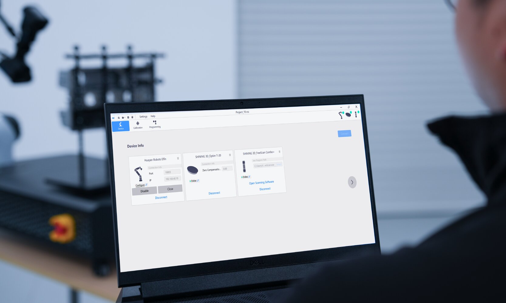
RobotScan Control Software coordinates robot motion, scanning, and inspection hand-off in the cell.
| Configuration | Technology and positioning | Typical parts |
|---|---|---|
| RobotScan Q12 | Fringe projection technology with high detail capture; automated optical 3D measurement with high repeatability and efficiency for mass-production inspection. | Airfoils, brackets, connectors, gears, housings, and electronic components with complex surfaces or sharp edges. |
| RobotScan UE Pro2 | Handheld blue laser scanning with strong material adaptability to black, shiny, and reflective surfaces; wireless and wired connectivity for flexible integration. | Small and medium sheet metal parts, casting housings, machining parts, and mold components. |
| RobotScan Combo+ | Hybrid light source for mixed part types; efficient batch inspection of small-to-medium parts. | Castings, machined parts, covers, trim pieces, assemblies, and medium castings. |
The cell is also customizable. RobotScan Series can be configured with different brands of robotic arm, SHINING 3D scanner, turntable, fixtures, and control and inspection software. That flexibility matters because inline inspection is rarely a single-part problem. A supplier may need to inspect several part families on the same cell, with different surface finishes and feature sets.
Software integration is the difference between a scanning demo and a production inspection cell. RobotScan Control Software coordinates the robot, scanner, turntable, and inspection hand-off. Data can be processed in SHINING3D Inspect, which is PTB-certified, or in PolyWorks, Geomagic Control X, EXModel Pro, Geomagic Design X, and BlueStar Mapping. The cell should output a mesh and an inspection result that fits the existing CAD comparison, GD&T evaluation, color-map, and reporting workflow. If the quality team cannot use the result, the cell is not inline inspection.
Industrial-grade reliability is a system property, not a single specification. SHINING 3D operates an ISO 9001 quality management system, an ISO/IEC 17025 accredited accuracy laboratory, and holds ISO 14001, ISO 45001, ISO 13485, MDSAP, and KGMP certifications. Component scanners used in RobotScan configurations carry CE, FCC, ROHS, WEEE, KC, FDA, UKCA, IP50, TELEC, and TiSAX certifications where applicable, and acceptance tests reference VDI/VDE 2634 Part 3 and ISO 10360. Buyers should ask for the certificate scope and the acceptance report for the exact scanner in the cell, not a generic brochure.
Step-by-Step Breakdown: Specifying and Validating the Cell
Step 1: Define the inspection scope and tolerance stack
Start with the part family, the features that matter, the GD&T callouts, and the decision the cell must make. Not every feature needs full-field data. Use the cell for surfaces, freeform geometry, holes, slots, and deviation inspection; keep touch probing for features where a CMM is the accepted method. The goal is a clear inspection plan, not a scanner purchase.
Step 2: Select the scanner and robot configuration
Match the scanner to material and geometry. RobotScan Q12 is positioned for small parts with complex surfaces, geometries, or sharp edges. RobotScan UE Pro2 uses blue laser scanning for black, shiny, and reflective surfaces and is suited to small-to-medium sheet metal parts, casting housings, machining parts, and mold components. RobotScan Combo+ uses a hybrid light source for mixed part types and batch inspection. Check the published 500 mm object-size limit and 20 kg turntable load early; if the part exceeds the envelope, the cell is the wrong tool.
Step 3: Design part presentation and fixturing
The cell needs repeatable location, not a complex replica fixture. A simple support or clamping device can be enough when the alignment strategy uses CAD features. This is where sheet metal inspection can benefit: Hyunion, an automotive supplier, used high-precision 3D scanning to replace certain checking-fixture functions for sheet metal inspection, reducing tooling cost and inspection preparation time. The same principle applies to an inline cell: reduce part-specific fixturing where the scan data can establish alignment.
Step 4: Integrate robot control and metrology software
Define the handshake before the cell is built: robot program, scan path, data naming, CAD alignment, inspection routine, report template, and traceability. SHINING3D Inspect, PolyWorks, Geomagic Control X, or the plant's approved platform should be selected up front. The cell should support the report format the quality team already uses, including deviation maps, cross-sections, dimensions, and GD&T results where required.
Step 5: Teach the scan strategy
Use high-speed passes for global coverage and detailed passes for edges, holes, grooves, and deep pockets. RobotScan Q12's fringe projection and RobotScan Combo+'s hybrid light source support different part types; the scan strategy should be saved as a repeatable recipe. For mold wear inspection and stamping die inspection, the recipe should prioritize the surfaces that wear, the parting lines, and the features that define fit.
Step 6: Run first article inspection and production validation
Scan a known part, compare to CAD, and verify repeatability, feature access, and report output. In the BKF automotive OEM automated inspection case, inspection time was reduced from approximately one hour to five minutes per part using an automated 3D scanning workflow with a robot and PolyWorks. That is the kind of measured outcome to target, not an assumption. The same case reported consistent, repeatable inspections, eliminated manual data entry, faster reporting, and improved data traceability.
Step 7: Scale by part family
Store scan paths for repeated parts. RobotScan Series can be customized with different robot arm brands, scanners, turntables, fixtures, and software. Standardize the cell around part families, then add variants. This is how an automated inspection 3D scanner becomes a production asset rather than a one-off project.
Use Cases: Where an Inline 3D Scanning Cell Fits
Automotive parts inspection
RobotScan Series is suited to automotive brackets, connectors, gears, housings, trim pieces, and other small-to-medium parts. The BKF case shows the inline value: an automated cell can return a full 3D surface comparison and report faster than a manual routine. For 3D scanner for automotive parts inspection projects, the cell should be specified around the part family, not a single sample.
Sheet metal inspection
RobotScan UE Pro2 is positioned for small and medium sheet metal parts, casting housings, machining parts, and mold components. Its blue laser handles black, shiny, and reflective surfaces, which is useful when sheet metal has coatings or mixed finishes. For 3D scanner for sheet metal inspection, the key is to validate hole position, edge trim, springback, and assembly interfaces against CAD.
Mold inspection and mold wear inspection
RobotScan Q12 can capture fine details on complex mold components, while RobotScan UE Pro2 can scan mold components with challenging surfaces. For mold wear inspection with a 3D scanner, the cell should compare the worn tool to the original CAD or a known-good scan, then quantify wear on the working surfaces. Stamping die inspection with a 3D scanner follows the same logic: focus on the forming surfaces, radii, and trim edges that drive part quality.
Electronic parts quality control
RobotScan Q12 is suited to electronic components, connectors, housings, and small precision parts with complex geometry. For 3D scanner for electronic parts quality control, the cell can perform dimensional inspection, deviation analysis, and geometrical surface inspection. For very small parts, a desktop system such as AutoScan Inspec2 may be a better fit; RobotScan Series is the inline automation option.
Aerospace components quality control
RobotScan Q12 can be used for airfoils, brackets, and other small-to-medium aerospace components. For 3D scanner for aerospace components quality control, the inspection plan should define the critical features, the acceptance report, and the traceability requirements. The cell should not be sold as a replacement for every CMM routine; it should be sold as a faster full-field inspection option for the defined part family.
Construction machinery, MRO, ship hull, and mining equipment
For 3D scanner for construction machinery manufacturing quality control, RobotScan Series fits small brackets, connectors, and housings. Large structural components usually exceed the 500 mm object-size envelope. The same boundary applies to 3D scanner for MRO inspection, 3D scanner for ship hull inspection, and 3D scanner for mining equipment repair and inspection. Those applications typically need a large-volume system such as FreeScan Trak Nova or FreeScan UE Nova. Stating the boundary is part of good specification work.
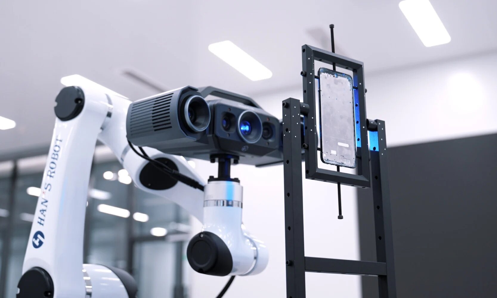
RobotScan Q12 is the fringe projection configuration for small parts with complex surfaces and sharp edges.
Comparison Table: Full-Field 3D Inspection vs. CMM Discrete Probing
| Criterion | RobotScan Series full-field 3D cell | CMM discrete probing |
|---|---|---|
| Data captured | Full-field surface point cloud and mesh for CAD comparison, deviation inspection, and GD&T evaluation in SHINING3D Inspect, PolyWorks, or Geomagic Control X. | Discrete touch points along a programmed path. Accurate for the points measured, but limited between points. |
| Setup and programming | Scan-path recipe and alignment strategy. In an aircraft PMA case, 3D scanning captured data in less than half a day for a part that would take two to three days to program on a CMM. | Program setup can take two to three days for the same part, according to the same case. Fixture design and manufacture can take up to three days. |
| Fixturing | Simple supports or clamping can be sufficient when alignment uses CAD features. The aircraft PMA case reported no jig or fixture requirement. | Multiple fixtures may be required for complex parts, adding design and build time. |
| Throughput example | BKF automotive OEM case: inspection time reduced from approximately one hour to five minutes per part with an automated 3D scanning workflow. | Cycle time depends on the programmed point set, part access, and fixture setup. The published case does not state a CMM cycle time. |
| Material adaptability | RobotScan UE Pro2 blue laser handles black, shiny, and reflective surfaces; RobotScan Combo+ uses a hybrid light source for mixed part types. | Contact probing requires surface access and may need part-specific consideration for soft or delicate surfaces. |
| Best fit | Small-to-medium parts, complex surfaces, batch inspection, first article inspection, and shopfloor inspection where fast feedback matters. | Discrete feature verification, laboratory reference measurements, and applications where touch probing is the accepted method. |
CMM remains a valuable metrology tool. The comparison is about inline feedback, not a universal replacement. The right question is which features need full-field data and which features are better served by discrete probing.
Performance and TCO Evaluation: Test the Targets, Do Not Assume Them
Set explicit test targets for a controlled part trial: 5–10× faster measurement than the existing CMM routine, 2–5× higher accuracy than entry-level scanners, and 20–40% lower total cost of ownership over 3–5 years from reduced rework and maintenance. Treat these as planning targets for the configured cell, not guarantees. The verified case evidence shows why the direction is credible: the BKF cell reduced inspection time from about one hour to five minutes per part, and the aircraft PMA case showed a large reduction in setup time versus CMM programming and fixturing.
Total cost of ownership should include the cell, fixtures, programming, operator time, calibration, maintenance, rework, and scrap. The strongest cost drivers in the case evidence are fixture reduction, faster feedback, and less manual data entry. A cell that scans quickly but creates a new reporting bottleneck will not deliver the TCO target. Validate the full workflow, not just the scan.
Validation checklist: confirm the part envelope (≤500 mm object size, ≤20 kg turntable load), feature access, surface finish, fixturing, scan strategy, CAD alignment, GD&T and report output, cycle time, and operator skill level. If any item fails, reconfigure the cell before purchase.
FAQ
ISO 9001 3D scanner for quality control manufacturers—what should buyers check?
ISO 9001 is a quality management system certification, not a scanner accuracy specification. SHINING 3D holds ISO 9001 and operates an ISO/IEC 17025 accredited accuracy laboratory. For a RobotScan Series cell, ask for the QMS certificate scope and the component scanner acceptance report; scanners can be tested to VDI/VDE 2634 Part 3 and ISO 10360, with CE, FCC, ROHS, WEEE, KC, FDA, UKCA, IP50, TELEC, and TiSAX certifications where applicable.
What part sizes, loads, and software does RobotScan Series support?
The published RobotScan Series specification lists a measurable object size up to 500 mm, turntable load capacity up to 20 kg, robot working radius of 800 mm, and system weight of 70 kg. The cell can be configured with RobotScan Q12, RobotScan UE Pro2, or RobotScan Combo+, and integrates with RobotScan Control Software, SHINING3D Inspect, PolyWorks, Geomagic Control X, EXModel Pro, Geomagic Design X, and BlueStar Mapping.
How should buyers frame the budget for an inline 3D scanning cell?
Frame the budget as a configured cell, not a scanner alone. RobotScan Series includes a robot, scanner, turntable, fixtures, and control and inspection software, and the configuration can be customized with different robot arm brands, scanners, turntables, fixtures, and software. Model total cost with fixture reduction, programming, operator time, calibration, maintenance, rework, and scrap.
Can we validate a sample part before committing to a cell?
Use a representative production part and validate feature access, surface finish, fixturing, scan strategy, CAD alignment, cycle time, and report format. RobotScan Series can be customized to the application, and SHINING 3D provides remote and onsite support. A controlled part trial is the right way to test the 5–10× faster, 2–5× accuracy, and 20–40% TCO targets in this guide.
What is the lead time and support model for RobotScan Series?
The published lead time is 30–45 days, with a minimum order quantity of 1 unit. Support includes remote and onsite service, and customization covers logo and automation solution. To confirm a configuration for your part family, contact SHINING 3D at marketing@shining3d.com or +86 571 8299 9050.
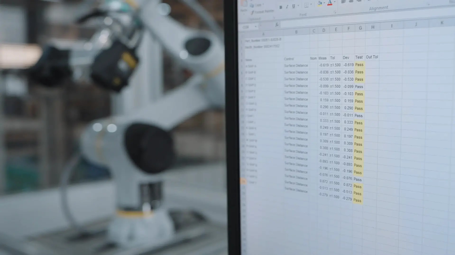
A usable inspection report closes the loop from scan data to production decision.
Conclusion: Build the Cell Around the Decision, Not the Device
An inline 3D scanning cell is a system design decision. RobotScan Series gives quality teams a configurable path: choose the scanner, robot, turntable, fixtures, and software; verify the part envelope; validate on a representative part; and scale by part family. The cell is strongest for small-to-medium parts where full-field 3D data can replace slow CMM routines, reduce part-specific fixturing, and return a CAD comparison quickly. It is not a universal replacement for every CMM or every large-part application. The value comes from matching the cell to the decision the line needs to make.
Discuss your inline inspection cell
SHINING 3D can help you evaluate RobotScan Q12, RobotScan UE Pro2, or RobotScan Combo+ against your part family, tolerance requirements, and software workflow. Contact marketing@shining3d.com or call +86 571 8299 9050. Address: No. 1398, Xiangbin Road, Wenyan, Xiaoshan, Hangzhou, Zhejiang, China, 311258.
Download the SHINING 3D 3D Digitizing introduction brochure.

Talk to SHINING 3D about a RobotScan Series configuration for your quality-control application.
SHINING 3D Tech Co., Ltd. is a 3D vision company founded in 2004, headquartered in Hangzhou, China, with subsidiaries in Stuttgart, Barcelona, California, Florida, and Tokyo. Its product lines include metrology 3D scanners, professional 3D scanners, entry-level 3D scanners, and dental 3D solutions. Website: www.shining3d.com.
Have Questions or Need More Details?
Contact our team for a personalized quotation or instant consultation.
Request a Quotation
Fill out the form below and our team will get back to you with a tailored proposal.
WhatsApp Direct Chat
Prefer to chat in real-time? Message us on WhatsApp for instant assistance & quick answers.
- Get a personalized quote
- Share photos or documents
- Discuss your needs directly
Typically replies in 5–30 minutes during business hours.