
3D Scanner for Quality Control vs. LiDAR: A Comparison Guide for Smart Manufacturing
A 3D scanner for quality control and a LiDAR system both output 3D point clouds, which is exactly why smart manufacturing buyers compare them, and exactly why the comparison so often goes wrong. They are engineered for different jobs. A metrology 3D scanner is built for high-precision 3D measurement and detailed surface capture; LiDAR is built for long-range spatial mapping and environment sensing. The trade-off is real: LiDAR covers more space, faster and further away, while a metrology scanner resolves far more dimensional detail per part and can have its accuracy verified against internationally recognised acceptance standards.
The decision rule for a manufacturing quality team is not which technology is better in the abstract, but what the data must be able to prove. If the point cloud has to be aligned to a CAD model, evaluated against GD&T tolerances, and converted into a traceable inspection report, the instrument required is a metrology-grade 3D scanner. If the point cloud has to support localisation, area mapping, obstacle awareness or robotic perception across a large environment, LiDAR is the appropriate sensing layer.
This guide sets out the trade-off, the standards that separate the two categories, and a practical selection framework for precision inspection versus environmental sensing.
The Real Problem: One Search Term, Two Different Measurement Jobs
3D scanning describes an output format, not a capability. Two systems can both return a dense point cloud and still be unable to substitute for one another, because fitness is determined by the measurement intent behind the data, not by the file extension.
A quality control workflow places specific demands on 3D data. The point cloud must:
- capture the complete surface geometry of the part, including freeform curves and complex internal features;
- be alignable to the original CAD model so dimensional deviations can be calculated rather than estimated;
- support deviation colour maps, cross-sections and feature-level evaluation, not just a visually convincing 3D replica;
- carry enough resolution to evaluate GD&T features, hole positions, edge profiles and surface flatness;
- produce repeatable, documented inspection reports that a quality management system can retain and audit.
LiDAR output is optimised for a different set of requirements: range, coverage, real-time awareness of a large space, and stable performance in outdoor or mobile conditions. That makes it valuable for autonomous movement, site mapping and machine perception. It also means LiDAR data is not normally specified or reverified through the optical 3D measuring system acceptance tests that industrial metrology depends on.
The failure mode is predictable. A manufacturer buys long-range sensing expecting inspection-grade answers and discovers the point cloud cannot support a tolerance decision. The consequences are not cosmetic: first article inspection results that cannot be defended, deviation analysis that misses sub-millimetre errors, and inspection records that do not satisfy a quality management audit looking for measurement traceability.
The opposite error is just as expensive. A metrology scanner used as a navigation sensor will do an excellent job of measuring a surface and a poor job of telling an automated vehicle where the walls are.
Why This Choice Has Become a Smart Manufacturing Decision, Not a Tooling Detail
Quality control has become the commercial centre of gravity for 3D scanning. The global 3D scanning market was estimated at USD 4.28 billion in 2024, driven by increasing use in quality control and prototyping, according to Grand View Research. Within that market, the quality control and inspection application segment held the largest share in 2024, per Precedence Research. The broader 3D metrology market, which includes 3D scanners for quality control alongside CMMs and sensors, was valued at USD 11.13 billion in 2024 by MarketsandMarkets.
Technology adoption reflects that demand pattern. Structured light scanners dominated the 3D scanner product segment in 2024 because of their precision in industrial applications, and short-range scanners at or below one metre held the largest share of the market on the strength of parts-inspection requirements. Automotive remains the largest end user of 3D scanning for parts inspection and quality control, while North America accounted for a 37% revenue share in 2024 and Asia Pacific is projected to be the fastest-growing 3D metrology region at an 8.0% CAGR through 2029.
The automation layer is expanding in parallel. The 3D automated optical inspection (AOI) equipment market was valued at USD 2.74 billion in 2024 and is growing at a 7.32% CAGR, with inline automated 3D inspection increasingly replacing offline checks in the electronics sector, according to Market Research Future and Mordor Intelligence. Metrology services, the outsourced complement to in-house systems, reached USD 852.3 million in 2024, with optical digital systems leading at a 61% share, per Grand View Research.
Two standards keep this field honest and are worth knowing by name:
- VDI/VDE 2634 Part 3 is the guideline for acceptance and reverification of optical 3D measuring systems based on multiple-view area scanning.
- ISO 10360-12 is the international standard specifically for verifying the performance of articulated arm CMMs equipped with 3D scanners.
On the supply side, Hexagon, FARO and Carl Zeiss are recognised as Tier 1 global leaders in the industrial metrology and 3D scanning market, according to SNS Insider. SHINING 3D, headquartered in Hangzhou, was recognised as an Emerging Leader in the global industrial metrology space by 360Quadrants in 2025 and reported 31% revenue growth in 2025 attributed to innovation in industrial metrology and global expansion.
The Decision Framework: Precision Inspection vs. Environmental Sensing
What a 3D scanner for quality control is engineered to do
A metrology 3D scanner captures the full geometry of a physical object without contact and converts it into data that can be compared against design intent. Several optical principles serve different inspection jobs:
- Laser line scanning operates on triangulation, adapts well to dark or reflective industrial surfaces, and typically delivers metrology-grade accuracy for quality control.
- Fringe pattern (structured light) scanning projects stripe patterns that deform across the surface; analysing those distortions reconstructs the object, making it well suited to small to medium parts with fine geometric detail.
- Speckle pattern scanning uses projected random dot patterns and stereovision, with strong ambient-light tolerance and marker-free operation.
- Photogrammetry reconstructs geometry from multiple 2D images and is best for large-scale object modelling; it is also the technique used to control cumulative error when scanning very large parts.
Industrial systems combine these principles. The SHINING 3D FreeScan Combo Series pairs blue laser and infrared VCSEL sources in a 620 g handheld body measuring 193 x 63 x 53 mm, offering four scan modes: 50 laser lines on the Combo+ (26 on the standard Combo), 7 parallel lines for detail, a single line for deep pockets, and a marker-free infrared mode. The FreeScan Trak Nova Series adds built-in video photogrammetry (VPG) so volumetric accuracy is maintained on large parts without coded markers.
What LiDAR is engineered to do
LiDAR is a long-range spatial mapping and environment sensing technology. Its value lies in telling a system what is around it, at distance, and in real time. That makes it foundational for autonomous navigation, site and corridor mapping, and machine perception. It is also why LiDAR performance is usually described in terms of range, coverage and refresh behaviour rather than dimensional tolerance against a CAD reference.
The two categories are therefore complementary more often than they are competitive. A plant may legitimately run LiDAR for automated guided vehicle navigation and a metrology scanner for the dimensional gate on incoming parts, on the same shopfloor, in the same year.
Six questions that settle the selection
- Will the data be compared with CAD and evaluated against tolerances? If yes, the requirement is metrology 3D scanning.
- Is the task navigation, area mapping or obstacle awareness? If yes, the requirement is long-range spatial sensing.
- What is the smallest feature that must be measured? If it sits in the tens-of-microns to sub-millimetre range, LiDAR is out of scope.
- What is the object size? Small parts under roughly 500 mm, medium-to-large components between 500 mm and 2500 mm, and extra-large structures above 2500 mm each point to a different scanner architecture.
- Does the quality management system require traceability? Only instruments with acceptance tests traceable to VDI/VDE 2634 and ISO 10360, performed in an ISO/IEC 17025 accredited laboratory, will satisfy that requirement.
- What environment and mobility does the inspection point need? Wireless and standalone operation, swappable batteries and shopfloor-grade protection levels change the practical answer.
How accuracy requirements translate into scanner classes
SHINING 3D's own selection guidance groups industrial accuracy needs into three tiers, which is a useful way to convert a tolerance requirement into a shortlist before any quotation is requested.
| Accuracy tier | Typical requirement | Typical scanner class |
|---|---|---|
| 0.005 - 0.02 mm | Functional safety parts, strict GD&T inspection, precision reverse engineering | Fixed blue light structured light systems and metrology handheld scanners |
| 0.02 - 0.05 mm | Assembly verification and structural analysis | Handheld 3D scanners, including wireless models |
| 0.05 - 0.1 mm | Overall deformation analysis, surface deviation mapping, large cosmetic parts | Tracking systems for expansive structures |
Step-by-Step: What a Metrology Inspection Workflow Actually Looks Like
Understanding the workflow is the fastest way to see where a long-range sensing system stops being useful.
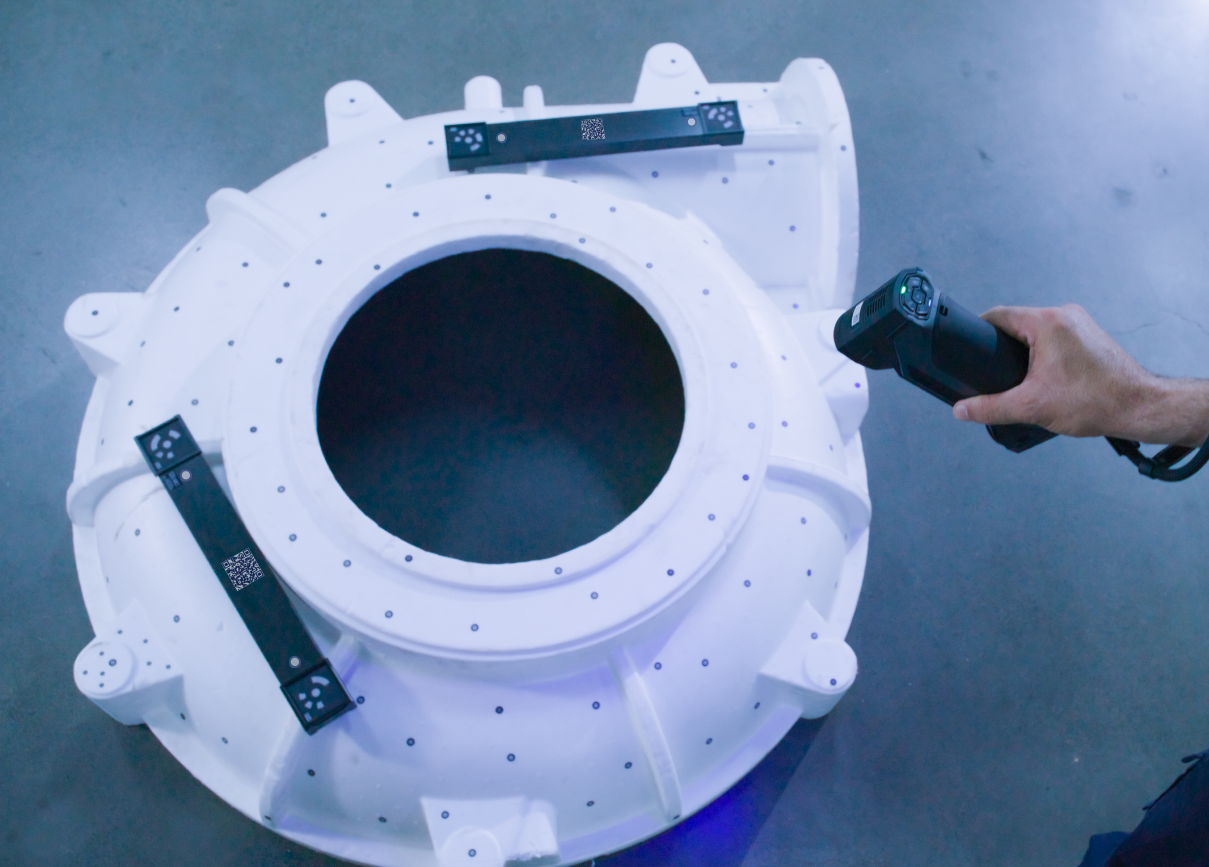
- 3D data acquisition. High-precision 3D scanners capture complex geometries, freeform surfaces and detailed features that are difficult to measure with traditional methods. This is the only step LiDAR superficially resembles, and even here the capture is performed at a working distance and resolution chosen for dimensional measurement rather than for area coverage.
- Data processing and alignment. Point cloud and mesh data are optimised, unnecessary information is removed, and the dataset is aligned so subsequent analysis is reliable. Alignment is what makes CAD comparison meaningful rather than decorative.
- CAD comparison, deviation analysis, dimensional inspection and GD&T evaluation. Scanned data is compared against the CAD reference to identify dimensional variation and manufacturing deviation, visualised through 3D colour maps. Critical dimensions, geometric features and tolerance requirements are then evaluated against engineering standards.
- Inspection results and report generation. Measurement results, deviation information and analysis data are organised into clear, traceable reports for review and documentation, which is the artefact a quality management system retains.
- Continuous improvement. Combining scanning, CAD comparison, dimensional measurement, deviation analysis and automated reporting converts inspection from a manual, labour-intensive task into a digital quality workflow.
SHINING3D Inspect, a PTB-certified inspection module, supports this chain with Compare, Cross-Section, Feature, Dimension, Gauges, Report and Quick Measurement functions, including an on-device version in the FreeScan Omni Series. Scanner data also flows into mainstream platforms including PolyWorks Inspector, Geomagic Control X, EXModel, Geomagic Design X and BlueStar Mapping, which matters when a quality team already has an established software workflow it does not want to rebuild.
Use Cases: Where Each Capability Earns Its Place
First article inspection and batch checks on small precision parts
The AutoScan Inspec2 is a fully automated desktop 3D inspection system with accuracy up to 0.01 mm, two 5MP industrial cameras, a blue LED light source, a maximum scan range of 140 x 90 x 80 mm and one-click automated scanning. Path storage lets operators save scanning paths for repeated parts so identical components can be batch-scanned with zero manual intervention, and a multi-object mode scans up to eight objects at once. It supports full-colour texture capture, integrates the PTB-certified SHINING3D Inspect module, and holds CE, FCC, ROHS, WEEE and KC certifications.
GD&T and full-field inspection of small-to-medium precision parts
The OptimScan Q12/Q9 fixed metrology scanner uses blue LED structured light and delivers 0.015 mm accuracy in large range and up to 0.005 mm in small range, with 4 x 12.3MP or 4 x 9MP cameras and dual scan range switching in one click. The OptimScan Q12/Q9 HD pushes this to 0.01 mm in large range and 0.004 mm in small range. Both use Monocular-Stereo Fusion (MSF) to increase data coverage at corners and joints, the areas where stereo scanners commonly produce gaps, and both support manual, semi-automated turntable and fully automated robot operation. Acceptance tests follow VDI/VDE 2634 and ISO 10360 in an ISO/IEC 17025 accredited laboratory.
Automated in-line inspection
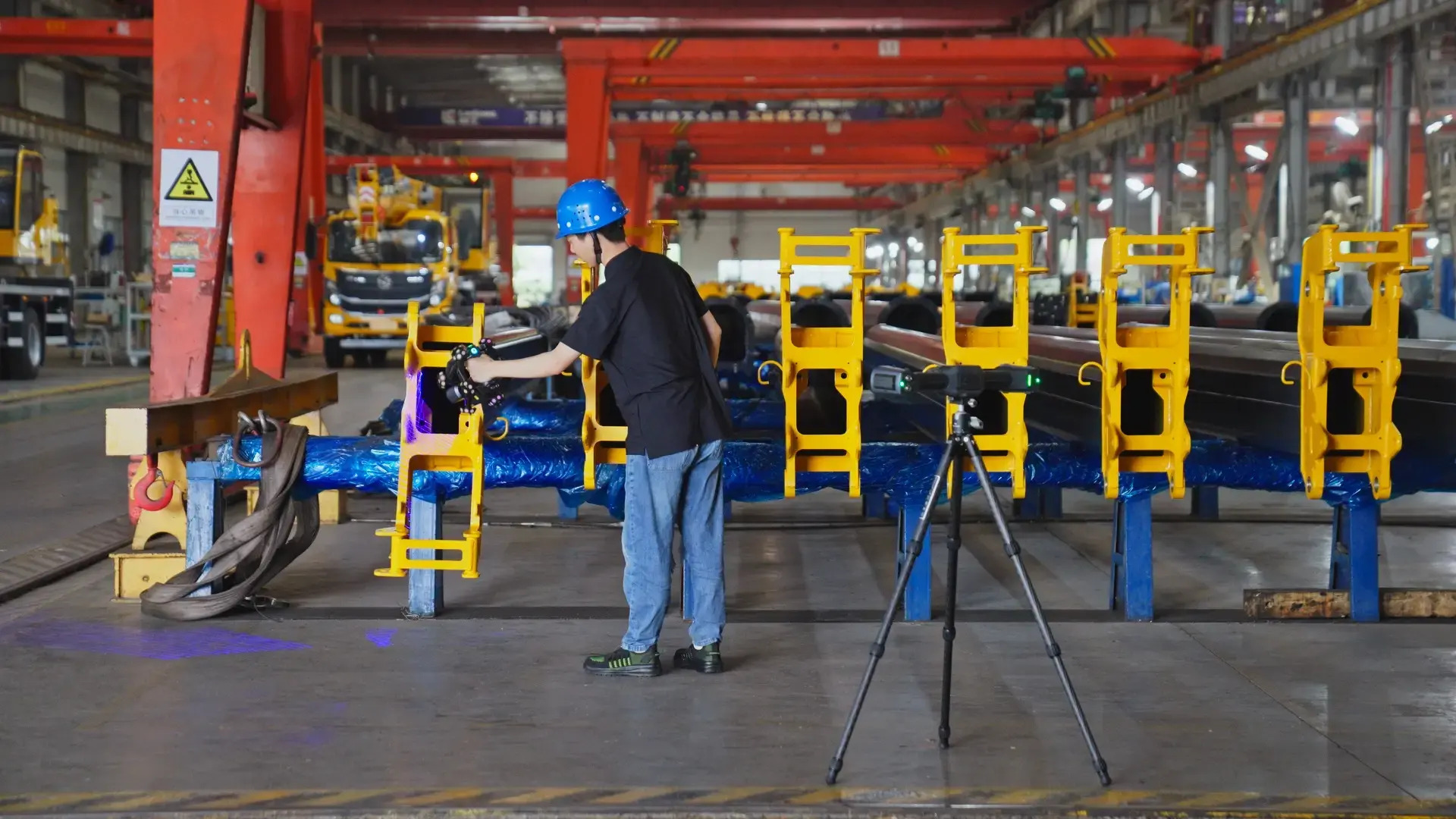
For repeat production inspection, the RobotScan Series integrates a high-accuracy 3D scanner, an industrial or collaborative robot, and control and inspection software. The published configuration supports measurable object sizes up to 500 mm, a turntable load capacity up to 20 kg and an 800 mm robot working radius. Three configurations map to different part families. RobotScan Q12 applies fringe projection for small parts with complex surfaces, geometries or sharp edges, such as airfoils, brackets, connectors, gears, housings and electronic components. RobotScan UE Pro2 uses handheld blue laser scanning for small and medium sheet metal parts, casting housings, machined parts and mold components. RobotScan Combo+ uses a hybrid light source for efficient batch inspection of mixed-size castings, machined parts, covers, trim pieces and assemblies. Components including robot arm, scanner, turntable, fixtures and software can be configured to the application.
Shopfloor and large-part inspection
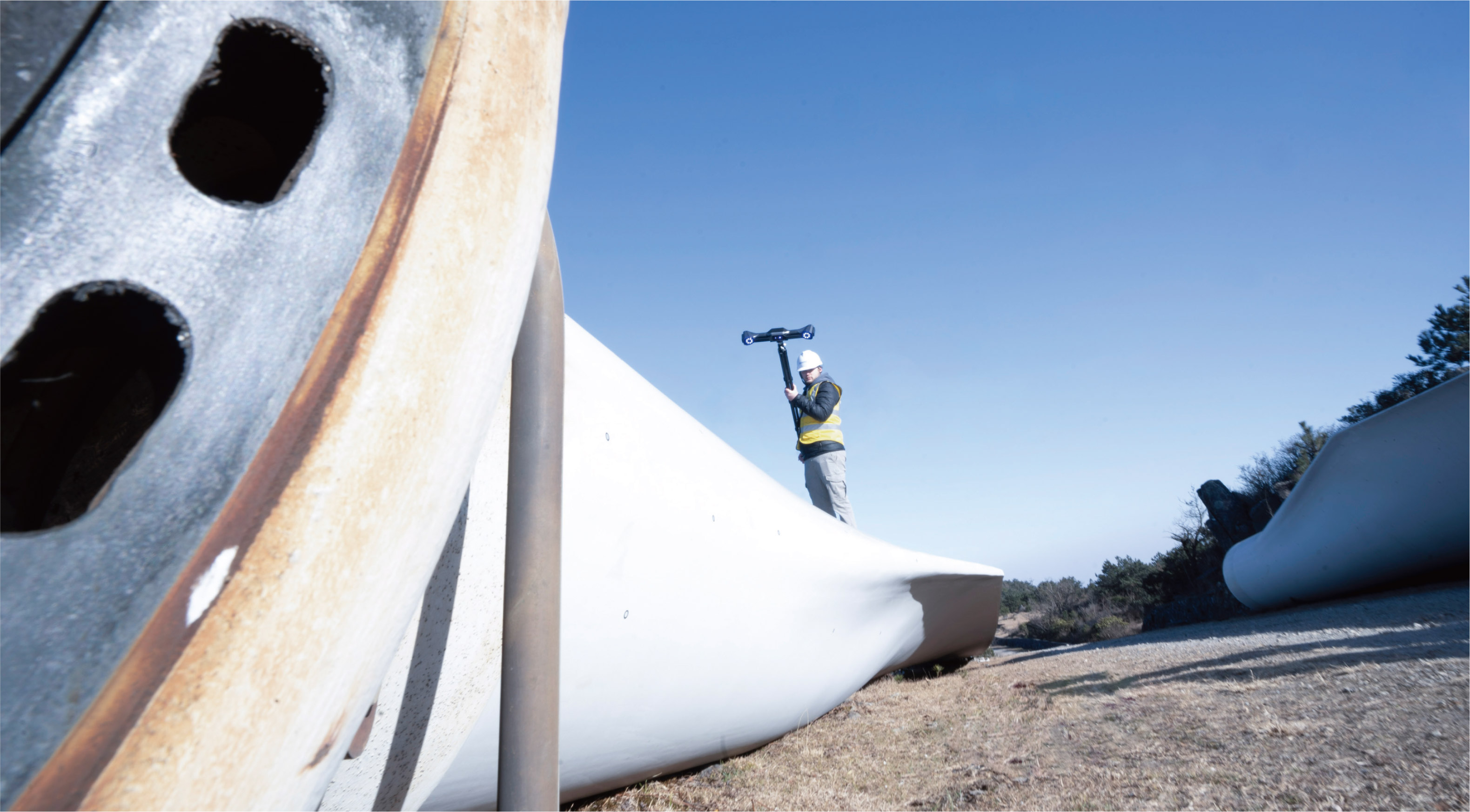
The FreeScan Trak Nova Series is a wireless dynamic tracking and scanning system with 0.02 mm accuracy, volumetric accuracy of 0.062 mm over 12 cubic metres, and 0.046 mm + 0.012 mm/m when VPG is used across extended volumes. It reaches 7,600,000 points per second, a flexible field of view up to 2600 x 2200 mm, and can scan without markers for most parts. The FreeScan UE Nova extends the same idea as a wide-area handheld scanner: 0.072 mm accuracy, 0.072 + 0.012 mm/m with VPG, 4,600,000 points per second, three selectable working ranges at 300 - 800 mm, 600 - 1500 mm and 1200 - 2600 mm, and a 1.6 kg body that can also be separated from the tracker for independent use.
On-site, laptop-free inspection
The FreeScan Omni Series is a standalone, wireless, inspection-ready metrology 3D scanner with on-device scan-to-inspect capability. It carries certified accuracy of 0.02 mm, volumetric accuracy of 0.02 + 0.015 mm/m with VPG, an integrated PTB-certified SHINING3D Inspect module, a 5.5-inch touchscreen, hot-swappable batteries and a net weight of 1.1 kg or less. Scanning, inspection and reporting can be completed entirely on the device, which is a workflow difference rather than a specification difference: the measurement happens where the part is.
Field, MRO and outdoor work
The FreeScan Combo+ Wireless and FreeScan Combo Wireless are wireless hybrid light source handheld scanners using the Wi-Fi 7 protocol for industrial-grade wireless data transmission. Both deliver 0.02 mm accuracy; with VPG, volumetric accuracy is 0.02 + 0.015 mm/m. The Combo+ Wireless reaches up to 9,106,000 points per second and the Combo Wireless up to 7,344,000 points per second, in a 550 g body with up to two hours of continuous scanning on hot-swappable batteries with a rapid-charging dock.
Validated outcomes from the shopfloor
Published case results show what changes when dimensional inspection moves onto the production floor:
- Construction machinery (LiuGong). Freeform exterior panels and structural components that could not be measured accurately with tape measures or calipers were captured with handheld 3D scanning; fixture verification moved onto the shopfloor with minimal disruption, and an operator cab was redesigned from a scan of the existing structure when original CAD data was unavailable.
- Metal casting (Zhongyan Casting). Full-size inspection before castings leave the factory, using the FreeScan Combo's 0.02 mm metrology-grade accuracy and four scanning modes, contributed to a product qualification rate of 99.5%.
- Automotive sheet metal inspection (Hyunion). Non-contact measurement and 3D reconstruction replaced part-specific checking fixtures, reducing tooling cost and inspection preparation time while improving measurement efficiency.
- Stamping parts (Yinrui). Because a typical checking fixture takes 1.5 to 2 months to design and build, replacing fixtures with a general-purpose 3D scanning system cut project time by at least one third.
- Electronic components (TDK Hungary). Combining a FreeScan Combo handheld 3D laser scanner with Geomagic Control X reduced prototype measurement time from roughly two weeks with outsourced partners, or 3 to 4 days with the internal measurement lab, to an average of 2 to 3 hours.
- Automotive OEM inspection cell (BKF, Vietnam). An automated workflow using a SHINING 3D handheld scanner mounted on a robotic arm and PolyWorks software reduced inspection time from about one hour to five minutes per part.
- Heavy equipment refurbishment (Steelstruct, Australia). Condition assessment of a 15-ton trommel screen shell returned from mineral processing plants moved from days to hours, with scan data compared directly against the original CAD model to identify deviations outside manufacturing tolerance.
Comparison Table: Metrology 3D Scanner vs. LiDAR for Quality Control
| Comparison dimension | Metrology 3D scanner (SHINING 3D class) | LiDAR |
|---|---|---|
| Primary design purpose | High-precision 3D measurement and detailed surface capture | Long-range spatial mapping and environment sensing |
| Typical measurement principle | Laser line, fringe pattern / structured light, speckle pattern, photogrammetry | Long-range optical ranging for spatial awareness |
| Accuracy expectation | Specified and verified per model, from 0.004 mm to 0.072 mm, with volumetric accuracy expressed as a formula such as 0.02 + 0.015 mm/m | Optimised for coverage and range rather than dimensional tolerance verification |
| Acceptance and traceability | VDI/VDE 2634 Part 3 and ISO 10360, tested in an ISO/IEC 17025 accredited laboratory; inspection reports and calibration certificates provided | Not typically accepted as the instrument of record for dimensional tolerance verification |
| Output consumed by | CAD comparison, GD&T evaluation, deviation colour maps and inspection reports via SHINING3D Inspect, PolyWorks or Geomagic Control X | Localisation, mapping, perception and navigation stacks |
| Relative speed and coverage | Higher dimensional detail per part; acquisition rate depends on model, up to 9,106,000 points/s on FreeScan Combo+ Wireless | Broader area coverage over longer distances per unit of time |
| Typical industrial role | First article inspection, in-line inspection, mold and die wear, sheet metal deviation, MRO and refurbishment | AGV and AMR navigation, site mapping, obstacle awareness |
The conclusion is not that one technology wins. It is that the two answer different questions, and only one of them answers the question a tolerance decision asks.
SHINING 3D metrology lineup for quality control
| Model | Accuracy | Acceptance / certification | Typical QC role |
|---|---|---|---|
| FreeScan Trak Nova Series | 0.02 mm; volumetric 0.062 mm (12 m³); 0.046 + 0.012 mm/m with VPG | VDI/VDE 2634 Part 3 & ISO 10360, tested in ISO/IEC 17025 accredited lab; CE, FCC, ROHS, WEEE, KC, FDA, UKCA, IP50, TELEC, TiSAX | Marker-free dynamic tracking of medium-to-large parts |
| FreeScan Combo+ Wireless / Combo Wireless | 0.02 mm; 0.02 + 0.015 mm/m with VPG | ISO 10360 certified, tested in ISO/IEC 17025 accredited lab; CE, FCC, ROHS, WEEE, KC, FDA, UKCA, IP50, TELEC, TiSAX | Wireless on-site inspection, confined spaces |
| FreeScan Combo Series | 0.02 mm; 0.02 + 0.033 mm/m; IR up to 0.05 mm | VDI/VDE 2634 Part 3 & ISO 10360; CE, FCC, ROHS, WEEE, KC, FDA, UKCA, IP50, TELEC, TISAX | First article inspection, mold and sheet metal work |
| FreeScan UE Nova | 0.072 mm; 0.072 + 0.012 mm/m with VPG | VDI/VDE 2634 Part 3 & ISO 10360; CE, FCC, ROHS, WEEE, KC, FDA, UKCA, IP50, TELEC, TiSAX | Large-volume, wide-area digitisation |
| FreeScan Omni / FreeScan Omni Lite | 0.02 mm; 0.02 + 0.015 mm/m with VPG | VDI/VDE 2634 Part 3 & ISO 10360; PTB-certified on-device inspection | Standalone scan-to-inspect without a laptop |
| OptimScan Q12/Q9 | 0.015 mm large range; up to 0.005 mm small range | VDI/VDE 2634 & ISO 10360 in ISO/IEC 17025 accredited lab; CE, FCC, ROHS, WEEE, KC, FDA, UKCA, IP50, TELEC, TISAX | Small-to-medium precision parts inspection |
| OptimScan Q12/Q9 HD | 0.01 mm large range; 0.004 mm small range | VDI/VDE 2634 Part 2 & ISO 10360 | Sub-5-micron GD&T on precision components |
| AutoScan Inspec2 | Up to 0.01 mm | PTB-certified SHINING3D Inspect module; CE, FCC, ROHS, WEEE, KC | Automated desktop batch inspection of small parts |
| RobotScan Series | Measurable object size ≤ 500 mm; turntable load ≤ 20 kg; robot working radius 800 mm | Configurable automation platform | Automated in-line inspection cells |
Frequently Asked Questions
How do I confirm that a 3D scanner for quality control meets ISO 9001 and traceability requirements?
Check two things: the manufacturer's quality management system and the acceptance test behind the scanner's stated accuracy. SHINING 3D operates a quality management system certified to ISO 9001, ISO 14001, ISO 45001, ISO 13485, MDSAP and KGMP, and holds Authorized Economic Operator (AEO) advanced certification for supply chain security. On the measurement side, models including the FreeScan Trak Nova Series, FreeScan Combo Series, FreeScan Combo+ Wireless and OptimScan Q12/Q9 are compliant with VDI/VDE 2634 and ISO 10360, tested in an ISO/IEC 17025 accredited accuracy laboratory, and supplied with inspection reports and calibration certificates traceable to those standards. Product-level certifications across the metrology range include CE, FCC, ROHS, WEEE, KC, FDA, UKCA, IP50, TELEC and TiSAX. VDI/VDE 2634 Part 3 covers acceptance and reverification of optical 3D measuring systems based on multiple-view area scanning, and ISO 10360-12 covers performance verification of articulated arm CMMs equipped with 3D scanners.
What can a metrology 3D scanner do that a LiDAR system cannot in a factory?
It resolves dimensional detail. SHINING 3D metrology scanners reach 0.02 mm accuracy on the FreeScan Trak Nova Series, FreeScan Combo Series, FreeScan Omni and FreeScan Combo+ Wireless; 0.015 mm large range and up to 0.005 mm small range on the OptimScan Q12/Q9; 0.01 mm and 0.004 mm on the OptimScan Q12/Q9 HD; and up to 0.01 mm on the AutoScan Inspec2 desktop system. That data feeds CAD comparison, GD&T evaluation, deviation colour maps and traceable inspection reports. LiDAR is designed for long-range spatial mapping and environment sensing, and its output supports localisation, mapping and perception rather than tolerance verification against a CAD reference.
What drives the cost of a 3D scanner for quality control?
Four things: accuracy class, object size, automation level and traceability. SHINING 3D's selection guidance notes that 3D scanner prices range from a few hundred dollars to tens of thousands, and that industrial inspection, which carries the highest accuracy requirement, typically starts from around twenty thousand dollars. Rather than budgeting against a single figure, budget by accuracy tier: 0.005 to 0.02 mm for functional safety parts and strict GD&T, 0.02 to 0.05 mm for assembly verification and structural analysis, and 0.05 to 0.1 mm for overall deformation and surface deviation mapping on large parts. Entry price rises with automation such as robot cells and turntables, with wireless or standalone capability, and with accredited calibration scope.
Can we validate a 3D scanner on our own parts before purchasing?
Yes, and validating on representative parts is standard practice in industrial metrology. SHINING 3D supports remote and onsite support, produces systems to order with a minimum order quantity of one unit, applies 100% testing, and offers OEM and ODM engagement including logo and automation solution customisation. The value of a part-specific trial is visible in published results: TDK Hungary reduced prototype measurement time to an average of 2 to 3 hours, and BKF reduced automated inspection time to five minutes per part. To arrange a part evaluation, contact campaign@shining3d.com.
What is the lead time and support coverage after ordering?
Lead time is 30 to 45 days, with a minimum order quantity of one unit. SHINING 3D is headquartered in Hangzhou, China, with subsidiaries in Stuttgart, Barcelona, California, Florida and Tokyo, an export ratio of 70% and main markets across the EU, USA and APAC. After-sales support is delivered through remote and onsite channels, and AEO advanced certification supports smoother customs clearance. Scanners are calibrated using certified artifacts or calibration panels traceable to metrology standards, and the SHINING3D Inspect software is continuously maintained and updated. To discuss a configuration and quotation, visit www.shining3d.com.
Conclusion: Choose the Instrument That Can Prove the Tolerance
The comparison between a 3D scanner for quality control and LiDAR resolves quickly once the question is stated properly. A metrology 3D scanner is designed for high-precision 3D measurement and detailed surface capture: it resolves features down to a few microns on the OptimScan Q12/Q9 HD, holds 0.02 mm accuracy across handheld and tracking platforms, maintains volumetric accuracy on large parts through video photogrammetry, and produces data that can be aligned to CAD, evaluated against GD&T and documented in a traceable report. LiDAR is designed for long-range spatial mapping and environment sensing, where coverage and awareness matter more than dimensional tolerance.
For smart manufacturing, the sensible architecture is not either/or. Long-range sensing keeps automated equipment moving safely through the plant. Metrology 3D scanning keeps the parts themselves defensible against drawing tolerances, from first article inspection through in-line batch verification, mold wear monitoring, sheet metal deviation analysis and MRO.
If the data has to survive a quality audit, the decision is settled: it needs a scanner whose accuracy is verified against VDI/VDE 2634 and ISO 10360 in an ISO/IEC 17025 accredited laboratory.
Next step: test the decision on your own parts
Send us a representative component and the tolerance it must meet. We will recommend the metrology configuration that fits, whether that is a wireless handheld scanner, a fixed blue light inspection system, a desktop automated unit or a robot cell, and return a sample inspection result you can compare against your current method.
Request a sample inspection or a quotation: campaign@shining3d.com | www.shining3d.com
Download the SHINING 3D 3D Digitizing introduction brochure: SHINING 3D_3D Digitizing introduction_20260523.pdf

Have Questions or Need More Details?
Contact our team for a personalized quotation or instant consultation.
Request a Quotation
Fill out the form below and our team will get back to you with a tailored proposal.
WhatsApp Direct Chat
Prefer to chat in real-time? Message us on WhatsApp for instant assistance & quick answers.
- Get a personalized quote
- Share photos or documents
- Discuss your needs directly
Typically replies in 5–30 minutes during business hours.