
3D Scanner for Quality Control: Certification and Specification Checklist
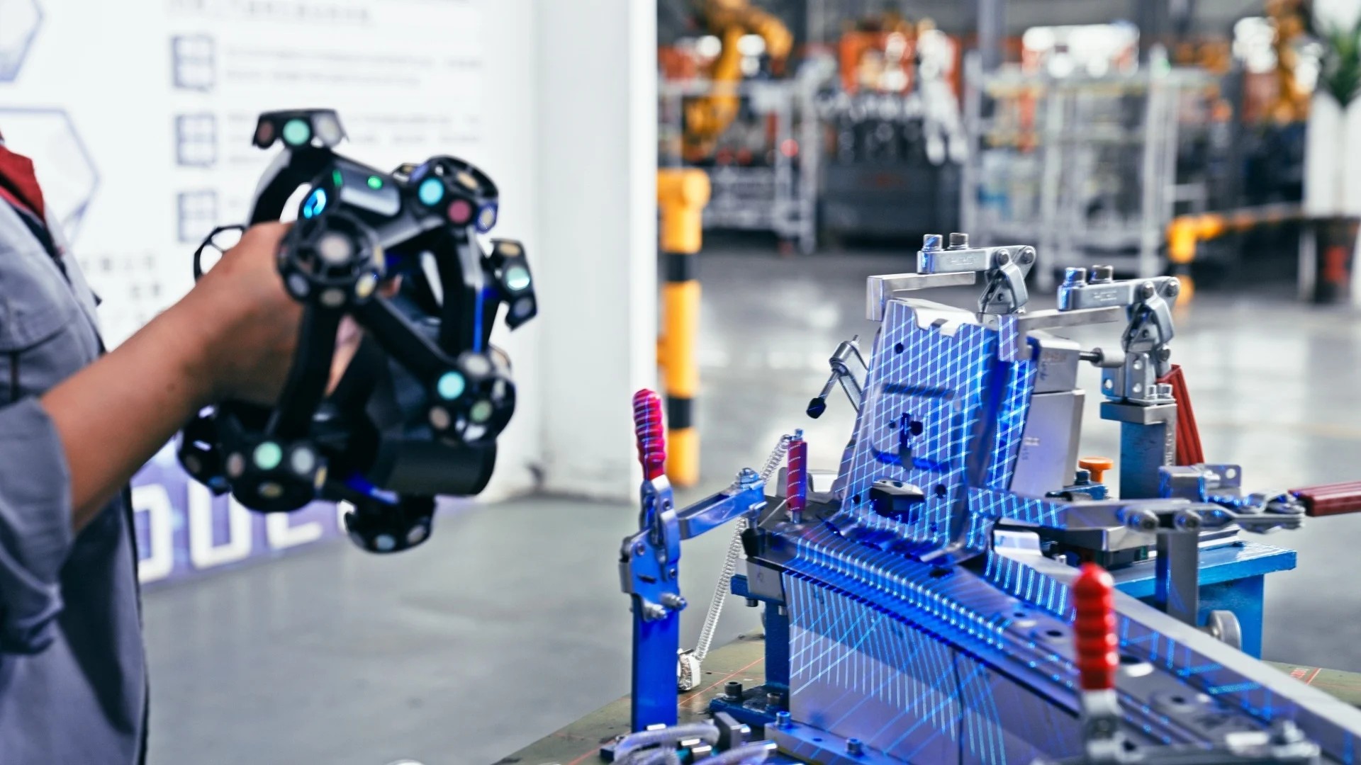
Scanning a stamped sheet metal part on a holding fixture with a wireless tracking 3D scanner
Quality-control engineers now evaluate 3D scanners differently from designers or reverse-engineering teams. In a QC environment, the scanner must produce measurements that can be compared with a CAD model, reported as pass or fail against a tolerance, and trusted enough to be used as a quality record. That places an unusual set of constraints on the technology: accuracy must be certified or at least traceable to recognized standards, repeatability must survive factory-floor conditions, and software must turn dense point clouds into deviation reports rather than just visual models.
This article is written as a selection checklist for manufacturing, quality, and metrology teams evaluating a 3D scanner for quality control. It focuses on standards, specifications, inspection scenarios, and the practical requirements that separate a measurement device from a general-purpose digitizer.
Why 3D inspection has become a core QC step
3D inspection is a non-contact measurement process that captures the full surface geometry of a physical object and compares that geometry with the reference CAD model. This detects dimensional deviations, warpage, assembly defects, and surface irregularities across the entire part, not just at selected points.
Market data explains why more plants are adding this capability. According to Grand View Research, the global 3D scanning market was estimated at USD 4.28 billion in 2024. Precedence Research reported that the quality control and inspection application segment held the largest market share in 2024. In automated production environments, manufacturers increasingly use 3D scanning for first article inspection, incoming inspection, in-line dimensional checks, and final quality gates.
For a QC manager the value is clear. A 3D scanner can digitalize a complete part in minutes, deliver color-coded deviation maps, and generate traceable inspection data that can be archived for compliance and process improvement.
What makes a scanner suitable for quality control
A QC-grade scanner should be judged first by whether it provides the evidence needed for an engineering decision. In practice, that means four constraints matter before comparing scan speed or software convenience:
- Metrological traceability: The scanner should be accepted or tested according to recognized optical metrology standards such as VDI/VDE 2634 or ISO 10360.
- Certified accuracy testing: Accuracy claims should be verified in a laboratory that follows ISO/IEC 17025 requirements.
- Compatibility with inspection software: The system should support CAD comparison, GD&T evaluation, dimensional measurement, and report generation.
- Workflow fit: The scanner should match the part size, part volume, and physical environment where inspections are actually performed.
These constraints explain why low-cost visual scanners are rarely suitable for signing off engineering reports even when they can render an attractive 3D model.
Compliance and quality standards for QC 3D scanners
When buyers compare suppliers who make 3D scanners for quality control, the documentation package is often the first differentiator. Three types of compliance are relevant.
Optical metrology acceptance standards
VDI/VDE 2634 and ISO 10360 are the standards most commonly used to verify the performance of optical 3D measuring systems. VDI/VDE 2634 Part 2 covers optical systems based on area scanning, while Part 3 covers multiple-view systems. ISO 10360-13 provides acceptance and reverification tests for optical 3D coordinate measuring systems.
SHINING 3D metrology scanners are tested against these frameworks. For example, the FreeScan Trak Nova Series is compliant with VDI/VDE 2634 Part 3 and ISO 10360, tested in an ISO/IEC 17025 accredited accuracy lab. The OptimScan Q12/Q9, FreeScan Combo Series, FreeScan Combo+ Wireless, and FreeScan Omni Series carry similarly documented acceptance testing.
Laboratory accreditation
The credibility of an accuracy figure depends on the laboratory that verified it. SHINING 3D operates a dedicated precision laboratory accredited according to ISO/IEC 17025 through CNAS. Because CNAS is a signatory to international mutual recognition arrangements, calibration certificates and test reports from this lab are accepted internationally. This is important for suppliers whose QC processes must satisfy automotive, aerospace, medical, or export requirements.
Product compliance certifications
Industrial scanners are also subject to regional electrical and safety regulations. Most SHINING 3D industrial scanners carry CE, FCC, ROHS, WEEE, KC, FDA, UKCA, IP50, TELEC, and TISAX certifications, depending on model and market. TISAX is particularly relevant for companies that exchange data with automotive OEMs because it addresses information security requirements across the supply chain.
Key specifications to compare before purchase
Specifications such as accuracy, precision, resolution, and volumetric accuracy are often grouped together as if they were one number. For QC applications, they need to be separated.
- Accuracy describes how close a measured value is to the true physical dimension. If a 100.00 mm feature is measured as 100.02 mm, the error is 0.02 mm.
- Precision describes repeatability: whether repeated scans of the same part generate consistent results under unchanged conditions.
- Resolution describes the smallest detail the scanner can distinguish. Higher resolution helps capture small features, but it does not automatically guarantee better dimensional accuracy.
- Volumetric accuracy describes how measurement error accumulates over the scanning volume. A formula such as 0.02 mm + 0.015 mm/m means that for a 2 m object, the total maximum error may be 0.05 mm.
For QC teams, accuracy alone is insufficient when inspecting large components. A scanner that is highly accurate over a 200 mm range may drift beyond acceptable limits when measuring a 2 m structural part. This is why volumetric accuracy and photogrammetry-based correction methods matter for large-object inspection.
Choosing a 3D scanner by QC application
The right scanner depends on the type of inspection, part size, and environment. Common QC scenarios covered by industrial metrology 3D scanners include first article inspection, automated in-line inspection, shopfloor inspection, mold inspection, sheet metal checking, GD&T verification, and large-part MRO dimensional analysis.
First article inspection and small precision parts
For small components with tight tolerances, fixed blue-light scanners provide high resolution and stability. The OptimScan Q12/Q9 uses a blue LED structured light source and delivers up to 0.005 mm accuracy in its small scan range. The OptimScan Q12/Q9 HD reaches 0.004 mm in small-range mode, making it suitable for fine edges, small holes, and micro features on consumer electronics, medical devices, and precision-machined parts.
For fully automated inspection of small parts, the AutoScan Inspec2 desktop 3D scanner combines a three-axis automated system, two 5 MP industrial cameras, and a PTB-certified SHINING3D Inspect module. It is designed for quality control of electronic components and similar small precision parts.
Shopfloor and on-site inspection
When parts cannot be moved to a metrology lab, portability and wireless operation become important. The FreeScan Combo+ Wireless and FreeScan Combo Wireless are handheld hybrid light-source scanners with 0.02 mm accuracy. The FreeScan Omni Series goes one step further: it is a standalone wireless metrology scanner with on-device PTB-certified inspection, allowing operators to complete scan-to-inspection workflows without a laptop.
These systems are common in automotive parts QC, sheet metal stamping, casting first-article checks, and engineering machinery structural inspection.
Automated and in-line inspection
Automated inspection cells combine a 3D scanner with a robot and turntable to achieve high repeatability and higher throughput. The RobotScan Series integrates SHINING 3D scanners, robotic arms, and inspection software to support batch inspection and in-line quality control. Fixed scanners such as the OptimScan Q12/Q9 can also be configured for robot-based inspection.
Large-part and complex-geometry inspection
For large castings, automotive body panels, molds, ship hull components, and heavy machinery parts, marker-free tracking and wide fields of view reduce preparation time. The FreeScan Trak Nova Series provides wireless dynamic tracking with 0.02 mm accuracy and does not require markers for most parts. The FreeScan UE Nova uses an ultra-large field of view of up to 2600 x 2200 mm, making data capture faster on large surfaces; its accuracy is 0.072 mm, with volumetric accuracy of 0.072 + 0.012 mm/m when video photogrammetry is used.
Aerospace quality control also uses handheld and tracking scanners for blade inspection, surface damage assessment, and MRO measurements. Consumer electronics inspection typically relies on desktop or fixed scanners because small parts with deep slots require detailed point spacing. The same product family can support multiple scenarios when a supplier offers both portable and fixed scanning platforms.
Example comparison of QC-focused SHINING 3D scanners
The table below summarizes how different scanner platforms address different QC constraints. All listed systems have acceptance testing according to VDI/VDE 2634 or ISO 10360 in an ISO/IEC 17025 accredited laboratory, unless otherwise noted in the original specification.
| System | Best QC fit | Stated accuracy | Scan speed / range | Key QC advantage |
|---|---|---|---|---|
| OptimScan Q12/Q9 HD | Very small parts, fine details, GD&T on precision components | 0.004 mm small range; 0.01 mm large range | Single shot under 1 s; small FOV 80x50 mm | Fixed structured-light stability and high resolution |
| OptimScan Q12/Q9 | Small to medium parts needing fixed, repeatable measurement | 0.005 mm small range; 0.015 mm large range | Single shot under 1 s; up to 430x300 mm large range | Dual scan range without manual lens change |
| FreeScan Combo+ Wireless / Combo Wireless | Cable-free shopfloor inspection of medium parts and assemblies | 0.02 mm | Up to 9,106,000 points/s (Combo+ Wireless) | Wireless hybrid blue laser and infrared VCSEL |
| FreeScan Omni Series | Standalone on-site scan-to-inspection without a laptop | 0.02 mm | Up to 7,619,000 points/s | Integrated PTB-certified on-device inspection |
| FreeScan Trak Nova Series | Large parts, automotive bodies, sheet metal, molds | 0.02 mm | Up to 7,600,000 points/s | Markerless wireless dynamic tracking |
| FreeScan UE Nova | Very large structures, shipbuilding and heavy machinery | 0.072 mm | 4,600,000 points/s; FOV up to 2600x2200 mm | Ultra-large FOV and high capture efficiency |
Practical workflow: from part to inspection report
Selecting hardware is only part of the QC deployment. To use a 3D scanner for quality control, most teams follow a digital inspection workflow:
- Acquire 3D data. Scan the part using the scanner and capture complete surface geometry.
- Process and align the data. Inspection software cleans the mesh, removes noise, and aligns the scan to the part coordinate system or reference CAD model.
- Compare scan to CAD. The software generates deviation color maps and highlights areas outside the tolerance band.
- Evaluate dimensions and GD&T. Features such as holes, slots, diameters, flatness, parallelism, position, and profile are measured and compared with engineering requirements.
- Generate a report. The system records pass/fail results, dimensional measurements, and visual evidence needed for a traceable quality record.
This workflow can be executed on a desktop PC or on the scanner itself when using a standalone inspection-ready system. Manufacturers that need to integrate inspection data with MES or quality databases should confirm which software formats are supported, such as STL, OBJ, PLY, P3, or ASC, and whether the inspection module can export standardized reports.
Procurement checklist for a QC-grade 3D scanner
During evaluation, consider the following points before committing to a platform:
- Define critical part size range and the tolerance level that the scanner must verify.
- Request a statement of acceptance testing, ideally to VDI/VDE 2634 or ISO 10360, from an ISO/IEC 17025 accredited lab.
- Test the scanner in the actual shopfloor environment, not only in a demo room.
- Include representative dark, shiny, or reflective parts in the test to confirm whether surface preparation is required.
- Check whether the scanner supports alignment and inspection modules compatible with PolyWorks, Geomagic Control X, or SHINING3D Inspect.
- Compare total workflow time: marker placement, spraying, scanning, processing, and reporting all affect throughput.
- Consider the future path to automation. Some scanners can be integrated with robotic arms and turntables for automated inspection cells.
- Review after-sales support. SHINING 3D offers remote support and onsite support, which may be needed during deployment in continuous production.
Real-world QC deployments with certified 3D scanners
Several real cases illustrate how certified 3D scanners address constraints in manufacturing quality control.
In Vietnam, automotive parts company BKF used an automated 3D scanning workflow for automotive parts inspection. By integrating a SHINING 3D scanner with a robotic arm, the company reduced inspection time from about one hour to five minutes per part, while improving repeatability and data traceability.
In China, sheet metal and tooling company Hyunion integrated high-precision 3D scanning into its quality management process. The implementation reduced reliance on dedicated part-specific checking fixtures and supported full-field dimensional inspection of critical sheet metal features such as holes, edges, and geometric tolerances.
In Australia, steel manufacturing company Steelstruct used SHINING 3D scanning systems for condition assessment and refurbishment of a 15-ton trommel screen shell. Inspection tasks that previously took days were completed in hours, and the scan data was compared directly against CAD to locate deviations requiring rectification. These examples point to a broader shift from contact or fixture-based measurement toward flexible, non-contact 3D inspection.
Frequently Asked Questions
Can a 3D scanner support ISO 9001 quality control documentation requirements?
Yes, if the scanner is used as part of a traceable measurement process. SHINING 3D operates an ISO 9001 certified quality management system, and its metrology-grade scanners are acceptance-tested against VDI/VDE 2634 or ISO 10360 in an ISO/IEC 17025 accredited Accuracy Laboratory. Inspection software can compare scanned data with CAD models, generate deviation color maps, GD&T results, and reports that can be stored as quality records.
What accuracy does a 3D scanner for quality control need?
For critical GD&T inspection and functional safety parts, accuracy around 0.005 to 0.02 mm is common. For assembly verification and structural analysis, 0.02 to 0.05 mm is generally enough. For overall deformation analysis of large surfaces, 0.05 to 0.1 mm may be acceptable. The required accuracy should be matched with the part tolerance and desired Six Sigma or process-control capability.
Are handheld or fixed 3D scanners better for production quality control?
A fixed scanner is often better for repetitive, high-precision inspection of smaller parts in a controlled environment. Handheld scanners are more suitable for large parts, complex geometries, on-site shopfloor work, or parts with curved surfaces where portability matters. For automated in-line inspection, the scanner can be integrated with a robot or turntable so that the process becomes repeatable and less dependent on operator skill.
Need a certified 3D scanning setup for your QC workflow? Contact SHINING 3D to discuss first article inspection, in-line automation, shopfloor scanning, or large-part dimensional analysis. A downloadable overview of SHINING 3D 3D digitizing solutions is available for engineering and procurement teams.
Download SHINING 3D 3D Digitizing Introduction (PDF)
Email: marketing@shining3d.com | Website: www.shining3d.com
Have Questions or Need More Details?
Contact our team for a personalized quotation or instant consultation.
Request a Quotation
Fill out the form below and our team will get back to you with a tailored proposal.
WhatsApp Direct Chat
Prefer to chat in real-time? Message us on WhatsApp for instant assistance & quick answers.
- Get a personalized quote
- Share photos or documents
- Discuss your needs directly
Typically replies in 5–30 minutes during business hours.