
How to Apply 3D Scanning for Quality Control in Tool & Mold Manufacturing
How to Apply 3D Scanning for Quality Control in Tool & Mold Manufacturing
3D scanning supports tool and mold quality control at three points in the production chain: verifying a mold, plug, or insert before it enters production, inspecting molded parts against nominal CAD, and monitoring surface change and wear across a mold's service life. A metrology-grade 3D scanner captures the full surface of a mold or component as dense point data in one measurement, and inspection software converts that data into dimensional deviations, geometric tolerances, and traceable reports.

Scanning a high-precision mold and a customized industrial equipment assembly with the FreeScan Trak ProW wireless dynamic tracking and scanning system.
This guide is written for quality engineers, mold shop managers, and manufacturing engineers who already own or are evaluating a metrology 3D scanner and need a working method rather than a product overview. It covers why conventional tools struggle with mold geometry, what a scanning system actually captures, how to match a scanning configuration to a mold size and tolerance class, and a six-step inspection workflow. It closes with four projects — including a ship mold surface inspection workflow in marine composite tooling — where scanning replaced or supplemented older measurement methods.
Problem Definition: Why Mold Quality Control Breaks Down with Conventional Tools
A mold is a freeform object by design. Core and cavity surfaces follow drafted, blended geometry; ribs, bosses, shut-offs, and deep pockets sit behind narrow openings; and the part produced depends on the mold being dimensionally correct along its whole surface, not at a handful of points. That mismatch between the shape of the object and the shape of the measurement tool is the root of most mold quality-control problems.
Three practical failure modes repeat across mold shops:
Point measurement against a surface requirement. Calipers, micrometers, height gauges, and pin gauges return discrete values. They confirm that a specific dimension is inside tolerance, but they cannot confirm that a blended cavity surface, a radius transition, or a whole parting-line profile is correct. Shape deformation between the measured points is invisible.
Programming and fixturing overhead. Coordinate measuring machines deliver high accuracy but require a program and a stable part orientation before the first data point is collected. In a Thailand aerospace component project, the same part required two to three days of CMM programming before data collection could begin, and in some cases fixturing design and manufacture added up to three more days. In an automotive stamping project, a typical dedicated checking fixture took one and a half to two months to design and build, and complex parts could require two separate fixtures. For tool and mold work — where the object being inspected is often the tool itself, and only one or two exist — that setup cost is difficult to justify.
Wear and surface condition. A mold changes during its life. Polishing, EDM texture, venting erosion, gate wear, and thermal fatigue all modify the working surface without changing any dimension that a gauge was designed to check. Traditional inspection detects wear late, after parts have already drifted.
Industry Background: The Mold Is the Origin of Every Dimensional Error
Tool and mold manufacturing sits upstream of nearly every formed, cast, or molded component. An error in a mold cavity is replicated across the entire production run, which is why dimensional inspection has shifted from sampling finished parts toward verifying the tooling that produces them.
The commercial context supports that shift. The global 3D metrology market was valued at USD 11.13 billion in 2024 and is projected to reach USD 15.01 billion by 2029 (MarketsandMarkets). Within the broader 3D scanning market, estimated at USD 4.28 billion in 2024, laser scanners accounted for 45.3% of total revenue (Grand View Research), and hardware — scanners and CMMs together — represented 66.7% of total 3D metrology revenue in 2023 (Grand View Research). In other words, the measurement instrument itself remains the center of gravity in industrial metrology investment.
Mold inspection also inherits an established workflow from adjacent industries. Ship mold surface inspection and post-molding quality control are already documented marine applications of the same optical measurement method, and the underlying task is identical: verify the tool surface before the molded object is produced from it, then verify the molded object against nominal CAD. Tool and mold manufacturing is now following the same path, because the geometry problem — large, curved, freeform surfaces held to tight tolerances — is the same problem.
SHINING 3D is a Chinese 3D vision technology company, founded in 2004 and headquartered in Hangzhou, that develops and manufactures metrology 3D scanners, professional 3D scanners, entry-level 3D scanners, and dental 3D solutions. The company operates a facility of nearly 140,000 square meters, employs 1,367 people including 533 engineers, holds more than 330 authorized patents and 230 software copyrights, and maintains an accuracy laboratory accredited in accordance with ISO/IEC 17025 for dimensional calibration and inspection. Its metrology scanners are tested against VDI/VDE 2634 Part 3 and ISO 10360, standards that define how optical 3D measuring systems and coordinate measurement machines are accepted and reverified.
Detailed Solution: What 3D Scanning Actually Captures in Mold Work
3D inspection is a non-contact, high-precision measurement process that captures the full geometry of a physical object using 3D scanning technology. By comparing the scanned 3D data with the original CAD model, manufacturers can detect dimensional deviations, assembly defects, warpage, and deformation. For mold work, that definition translates into four concrete deliverables:
1. Full-field surface data. Instead of a set of points, the scanner returns a dense point cloud that is meshed into a continuous surface model. Every point on that surface can later be compared to CAD, so a question asked six months after the scan can still be answered from the archived data.
2. CAD comparison and deviation mapping. The scanned mesh is aligned to nominal CAD and expressed as a color deviation map. Areas outside tolerance appear immediately, which is what makes it possible to distinguish a global offset from a local defect such as a sink mark, an undercut, or a stepped parting line.
3. Dimensional and GD&T evaluation. Advanced inspection software supports detailed dimensional inspection and GD&T analysis, so critical dimensions, geometric features, and tolerance requirements can be evaluated against engineering standards — not just against the CAD surface.
4. Traceable reporting. The final stage of the workflow is generating clear, traceable inspection reports that organize measurement results, deviation information, and analysis data for engineering and quality teams.
Volumetric accuracy: the number that matters on a large mold
When a mold is one meter long rather than ten centimeters, single-point accuracy is no longer the governing figure. Volumetric accuracy describes measurement accuracy across a larger scanning volume. For a scanner specified as 0.02 mm + 0.015 mm/m, measuring a two-meter-long object gives an expected maximum error of 0.02 + (0.015 × 2) = 0.05 mm over the full length. Cumulative error grows with object size, which is why global measurement strategies — global markers and video photogrammetry (VPG) — matter for large tooling.
Video Photogrammetry (VPG) is the current form of this control technique. Traditional photogrammetry uses multiple static images to build a high-accuracy marker and coded-target framework; VPG replaces hundreds of static images with continuous video capture, and continuously optimizes the spatial position of reference markers during scanning. The practical effect is stable volumetric accuracy on large molds without the time cost of coded-marker workflows.
Light sources and surface condition
Mold surfaces are rarely cooperative. Blue laser light has low sensitivity to ambient light and surface reflectivity, which is why it is well suited to industrial inspection of dark, polished, or reflective tool steel without scanning spray. Blue LED structured light projects grating patterns to capture dense surface data and excels at fine textures, complex geometry, and small details — the reason it is used on small precision inserts and fine molded features.
Step-by-Step Breakdown: A Six-Step Mold Inspection Workflow
The workflow below is a general digital inspection sequence adapted to tool and mold manufacturing. Steps 1 and 2 are performed with the scanner; steps 3 to 5 are performed in inspection software such as SHINING3D Inspect, PolyWorks Inspector, or Geomagic Control X.
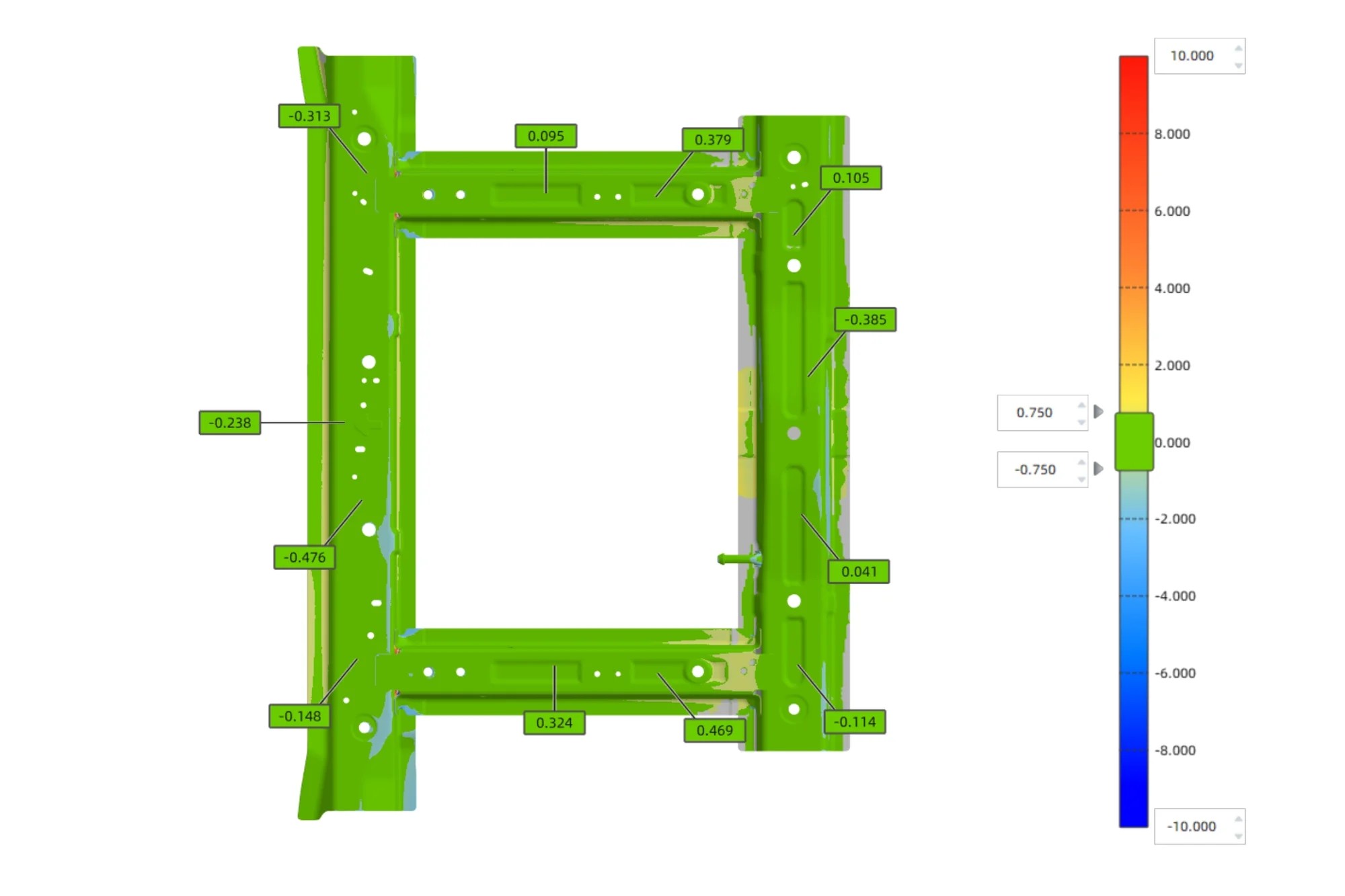
Inspection output after CAD comparison: deviation analysis turns scan data into an actionable, reportable result.
Choosing the Right Scanning Configuration for Tool and Mold Work
Mold geometry sets the constraints, and the constraints should drive the scanner choice. Three questions cover most of the decision:
How big is the tool, and how tight is the tolerance? Object size is the primary filter. Small parts below roughly 500 mm call for systems focused on intricate internal cavities and fine geometry. Medium to large components require portable scanning solutions. Extra-large structures require scanners with an expansive tracking volume to maintain consistency over large areas.
Can markers or fixtures be applied? On a one-off mold or a legacy tool with no digital documentation, marker application and part fixturing may be impractical or simply too slow. Marker-free dynamic tracking determines the scanner's spatial position with an optical tracker, which drastically reduces preparation time.
What is the surface condition? If the mold surface is dark or highly reflective and scanning spray cannot be used, blue laser and hybrid light sources handle those materials directly. If the feature is exceptionally small, high-resolution blue structured light remains the appropriate choice, since capturing micro-detail takes priority over surface convenience.
Comparison table: matching SHINING 3D scanner configurations to mold tasks
| Configuration | Scanner | Stated accuracy | Mold QC task it fits | Relevant capability |
|---|---|---|---|---|
| Wireless dynamic tracking | FreeScan Trak ProW+ | 0.023 mm; volumetric accuracy with VPG 0.044 mm + 0.012 mm/m | Medium-to-large molds, mold bases, customized industrial equipment, high-precision tooling surfaces | Marker-free scanning, wireless operation, 7,600,000 points/s, resolution 0.01–10 mm |
| Wireless dynamic tracking | FreeScan Trak Nova Series | 0.02 mm; volumetric accuracy with VPG 0.046 mm + 0.012 mm/m | Large molds and full-size molded components; detachable scanner for flexible access | Flexible FOV up to 2600 × 2200 mm, 62 laser lines high-speed, VPG marker-free tracking |
| Handheld hybrid light source | FreeScan Combo Series | 0.02 mm; volumetric accuracy 0.02 + 0.033 mm/m | Injection molds and die-casting molds, small-to-medium tooling, deep pockets, detail capture | Blue laser + infrared VCSEL, 620 g, multiple scan modes including single-line for deep pockets |
| Wireless handheld hybrid | FreeScan Combo+ Wireless / FreeScan Combo Wireless | 0.02 mm; volumetric accuracy with VPG 0.02 + 0.015 mm/m | Shop-floor mold checks where cable-free mobility is required | Wi-Fi 7 connection, 93 laser lines, up to 9,106,000 points/s, 550 g, hot-swappable battery |
| Fixed blue structured light | OptimScan Q12/Q9 HD | 0.004 mm small range; 0.01 mm large range | Small precision inserts, cores, fine molded features, mold wear and lifecycle monitoring | 4 × 12.3 MP cameras, blue LED, monocular-stereo fusion, dual range one-click switching |
| Automated desktop | AutoScan Inspec2 | Up to 0.01 mm | Batch inspection of small molded parts and repeated components | 3-axis automated scanning, path storage for batch scanning, PTB-certified inspection module |
All configurations listed above are acceptance-tested against VDI/VDE 2634 and ISO 10360 in an ISO/IEC 17025 accredited laboratory, and all provide inspection reports and calibration certificates traceable to those standards, subject to the actual certificates issued.
Use Cases: How Mold and Tooling Manufacturers Apply Scanning
High-precision molds and customized industrial equipment — Thailand
A manufacturer of industrial machinery specializing in high-precision molds and customized industrial equipment in Thailand has used the FreeScan Trak ProW system for inspection tasks for over a year, with one unit in service. The system's marker-free scanning and wireless operation enabled high-resolution data acquisition at up to 0.023 mm accuracy on complex and large workpieces. Inspection time dropped from 30–45 minutes to 10–15 minutes per part, and overall 3D inspection efficiency improved by approximately 60%. The resulting scan data integrated with CAD/CAM workflows to support reverse engineering, quality inspection, and design validation.
The notable part of that result is not the accuracy number — it is the preparation time that disappeared. Marker-free scanning removed the setup that previously dominated the cycle, and wireless operation let the scanner go to the mold rather than the reverse.
Tooling and prototype measurement — Hungary
An electromagnetic interference (EMI) filter development and manufacturing factory in Hungary adopted the FreeScan Combo handheld 3D laser scanner together with Geomagic Control X inspection software for prototype inspection and measurement. The required measurements became feasible, with turnaround reduced from approximately two weeks with outsourced external partners, or three to four days with the internal measurement lab, to an average of two to three hours. The scanner captures complete surface data, which also means future checks remain possible even when a physical prototype is no longer available.
Ship mold surface inspection and post-molding quality control — a comparable marine workflow
Marine composite tooling provides the closest published analogue to tool and mold workflow, because the objects are large, curved, and few in number. A full-service engineering and manufacturing company specializing in advanced composite tooling, design, and fabrication in the United States uses the FreeScan Trak Nova for digital manufacturing of marine molds. The team scans physical assets that lack digital documentation, producing accurate surface models that serve as the foundation for reverse engineering, CAD modeling, and full documentation.
The critical control point is pre-casting verification. Using PolyWorks Inspector, the team validates that CNC-machined plugs match the intended CAD models before mold casting begins — preventing costly downstream errors. Traditional handheld scanners often struggle to maintain accuracy and stability on large, curved surfaces such as boat hulls and deck molds, which is exactly the geometry class that tracking systems with VPG are built for.
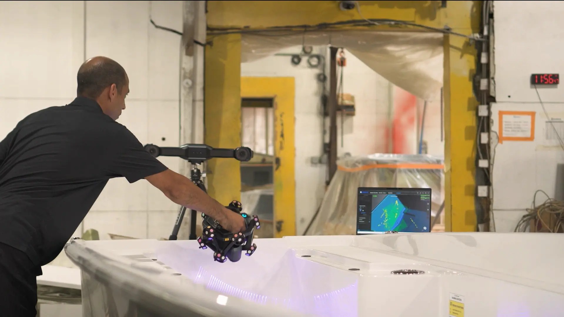
Ship mold surface inspection: the same large-curved-surface workflow applies directly to tool and mold manufacturing.
Post-molding and casting inspection before shipment — China
An aluminum, copper, and other metal casting manufacturer in China uses the FreeScan Combo to perform full-size inspections before castings leave the factory. The company reports that metrology-grade accuracy of 0.02 mm supports consistent, high-precision results for full-size inspection, that the scanner's robustness allows 3D data of castings to be captured directly on the production floor, and that multiple scanning modes cover all types of workpieces. The result reported is an improvement in product qualification to 99.5%, alongside gains in both quality and production efficiency.

Closing the loop: inspection data feeds directly back into production adjustments.
Prototype and legacy data capture — why the archive matters
In a project involving an EMI filter factory, the scanner captured complete surface data that enabled future checks even when physical prototypes were unavailable — a capability already used for product refinements. For mold shops, the equivalent value is a digital record of the mold at approval. When a quality issue appears six months into a production run, there is a baseline to compare against, and the question shifts from "is the mold correct?" to "what changed?"
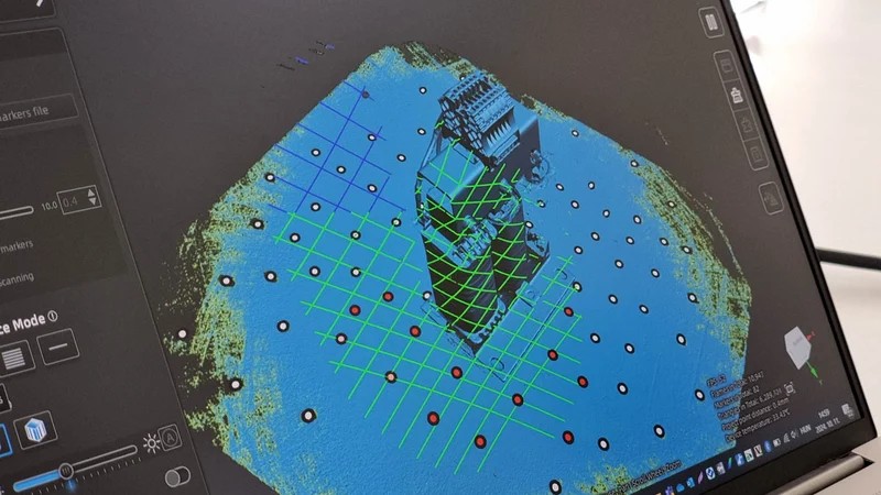
Inspection software converts scan data into dimensional analysis. Compatible platforms include SHINING3D Inspect, PolyWorks Inspector, and Geomagic Control X.
Frequently Asked Questions
Yes. SHINING 3D metrology scanners provide inspection reports and calibration certificates traceable to international standards such as VDI/VDE 2634 and ISO 10360, subject to the actual certificates issued. All calibration and verification procedures are performed in the company's accuracy laboratory, which operates in accordance with ISO/IEC 17025 requirements. VDI/VDE 2634 Part 3 is the primary standard for evaluating the accuracy of optical 3D measuring systems based on area scanning, and ISO/IEC 17025 accreditation is a critical verification requirement for laboratories publishing 3D scanner accuracy data.
The choice follows object size, tolerance class, and surface condition. For medium-to-large molds, mold bases, and customized industrial equipment, the FreeScan Trak ProW+ is specified at 0.023 mm accuracy with VPG volumetric accuracy of 0.044 mm + 0.012 mm/m, and was used in a Thailand mold inspection project that reduced per-part inspection time from 30–45 minutes to 10–15 minutes. For large molds and full-size molded components, the FreeScan Trak Nova Series offers 0.02 mm accuracy and a flexible field of view up to 2600 × 2200 mm. For injection molds, die-casting molds, and small-to-medium tooling with deep pockets, the FreeScan Combo Series provides 0.02 mm accuracy from a 620 g handheld body with blue laser and infrared VCSEL sources. For small precision inserts and fine features, the OptimScan Q12/Q9 HD reaches 0.004 mm in small range mode with four 12.3 MP cameras.
The cost of 3D scanners varies widely, and industrial inspection has the highest accuracy requirements and harshest manufacturing environment, with budgets typically starting from twenty thousand dollars for industrial-grade systems. Beyond the scanner itself, the practical investment includes inspection software and operator time. On that second point, one Thailand-based user noted that at most half a day is needed to become familiar with operating the system, and that the interface was found easy to use even by team members without specialized 3D scanning skills. In a Latin America mining-equipment project, the client reported that the FreeScan Trak Nova offered an excellent balance between performance, capability, and investment value compared with alternative solutions.
Yes. SHINING 3D supplies metrology 3D scanners with a minimum order quantity of one unit and a typical lead time of 30–45 days, with production modes covering OBM and ODM, and customization available for logo and automation solutions. Quality control procedures include 100% testing of products. After-sales coverage includes both remote support and onsite support, and the scanners integrate with mainstream inspection platforms — SHINING3D Inspect, PolyWorks Inspector, and Geomagic Control X — so a trial scan can be evaluated inside the software your quality team already uses.
Conclusion: Measure the Mold, Not Only the Part
Applying 3D scanning to tool and mold quality control is not a matter of replacing a caliper with a scanner. It is a change in what gets measured. Instead of sampling dimensions on finished parts and inferring the condition of the tool, the mold itself becomes a measurable, archivable surface. Every molded part produced afterward inherits a known baseline.
The method has three requirements. First, full-field data capture, because mold geometry is freeform and point measurement cannot see between the points. Second, traceable accuracy, because a deviation figure is only useful if it can be defended in front of a customer or a certification body — which is why VDI/VDE 2634 Part 3 and ISO 10360 acceptance testing in an ISO/IEC 17025 accredited laboratory matters more than a headline accuracy number. Third, workflow fit, because the fastest scanner on paper is worth little if it needs two days of programming or three days of fixturing before it produces a number.
Tool and mold manufacturers do not need to build this capability from nothing. The workflow is already established in adjacent industries — including ship mold surface inspection and post-molding quality control, where CNC-machined plugs are validated against CAD before mold casting begins. The geometry problem is the same, the standards are the same, and the measurement data is compatible with the same inspection software. The remaining step is applying it one stage earlier in the production chain, to the tool itself.
Next Step: Scan Your Own Mold
Send a mold, insert, or molded sample for a trial scan, or request a quote for the configuration that matches your tool size and tolerance class. A SHINING 3D engineer can review your CAD and inspection requirements and recommend a scanning setup — handheld hybrid, wireless dynamic tracking, or fixed structured light.
Email: marketing@shining3d.com
Tel: +86 571 8299 9050
Website: www.shining3d.com
Download the 3D Digitizing introduction brochure: SHINING 3D_3D Digitizing introduction (PDF)

Have Questions or Need More Details?
Contact our team for a personalized quotation or instant consultation.
Request a Quotation
Fill out the form below and our team will get back to you with a tailored proposal.
WhatsApp Direct Chat
Prefer to chat in real-time? Message us on WhatsApp for instant assistance & quick answers.
- Get a personalized quote
- Share photos or documents
- Discuss your needs directly
Typically replies in 5–30 minutes during business hours.