Why Your Calipers Are Slowing Down QC: A Metrology 3D Scanner Fix
A caliper answers one question per stroke. A metrology 3D scanner answers every dimensional question about a part in one pass, and it does so without touching the workpiece. For a quality team under pressure to release parts faster, that gap is usually where the bottleneck lives.
The fix is not to read the caliper faster. It is to change the measurement method. 3D inspection is a non-contact, high-precision measurement process that captures the full geometry of a physical object using 3D scanning technology: by comparing the scanned 3D data with the original CAD model, manufacturers can detect dimensional deviations, assembly defects, warpage, and deformation. The throughput effect is documented in real deployments. At an industrial machinery manufacturer producing high-precision moulds and customized equipment, per-part inspection time fell from 30–45 minutes to 10–15 minutes, and overall 3D inspection efficiency improved by approximately 60%. At an EMI filter factory, prototype measurement that previously took 3–4 days in an internal lab, or roughly two weeks through external partners, dropped to an average of 2–3 hours.
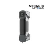
A metrology-grade handheld 3D scanner replaces point-by-point contact checks with a full-surface digital record.
Where a Caliper Stops Being Enough
Hand tools are highly efficient for quickly checking basic dimensions. A caliper is the right instrument for a simple geometry, such as the diameter of a tube. The limitation appears when the quality question shifts from “how wide is this feature” to “does this surface match the design” — the complete 3D profile of complex curvatures and intricate freeform surfaces.
Four failure patterns show up repeatedly in QC workflows built on contact measurement:
- Two-point geometry only. A caliper measures the distance between contact points. Warpage, twist, springback, R-angle transitions, and cross-section profiles stay invisible, so a part can pass every key-point check and still fail at assembly.
- Contact force on thin or soft parts. Traditional fixtures and gauges often use probes that touch the part surface. For thin, easily deformed stamping parts, that contact carries risk; a non-contact scanner captures geometry without any physical pressure and keeps the part in its original condition.
- Shape deviations that key-point checks miss. Full-surface measurement detects shape deformations that are often missed in key-point checks and reduces operator-dependent error.
- Data that cannot travel. A number written on a route card cannot be overlaid on a CAD model, re-checked next year, or sent to a customer as evidence.
There is also the tooling tail. Verifying a stamped or cast part with a dedicated gauge usually requires a part-specific fixture: in one automotive stamping project, fixture development took 1.5 to 2 months per part, custom fixtures cost thousands of dollars each, and complex parts could require two separate fixtures. None of that time appears in the measurement itself, but all of it delays release.
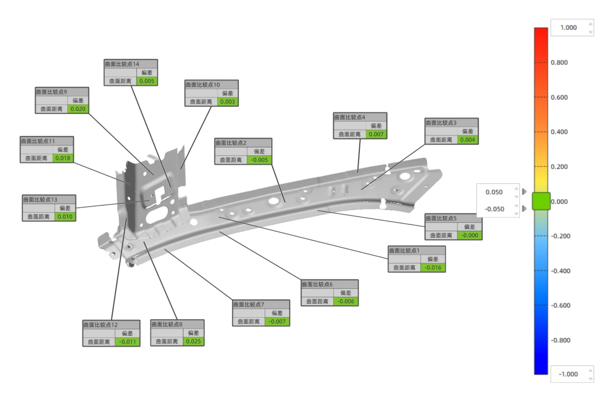
A deviation color map answers a question no caliper can: where the whole surface sits relative to the CAD model.
What calipers are still for
No single measurement technology suits every inspection task. Calipers stay efficient, immediate, and inexpensive for simple dimensional checks on simple geometries, and they will not disappear from the shop floor. The decision rule is straightforward: use contact hand tools for basic two-point dimensions, and use a metrology-grade 3D scanner when the requirement is the part’s full geometry, its deviation from CAD, or a traceable digital record of the measurement.
Why This Became a Bottleneck Now
The economics of measurement have shifted. The global 3D scanning market was estimated at USD 4.28 billion in 2024, with laser scanners accounting for 45.3% of total revenue (Grand View Research). The wider 3D metrology market was valued at USD 11.13 billion in 2024 and is projected to reach USD 15.01 billion by 2029 (MarketsandMarkets), with hardware — scanners and CMMs — representing 66.7% of total 3D metrology revenue in 2023 (Grand View Research).
Adoption concentrates where tolerances are tight. Automotive was the largest end-user segment for 3D scanning in 2024, using scanners for in-line inspection and reverse engineering (Precedence Research), and reverse engineering dominated the application market overall as legacy parts continue to be digitized (Grand View Research). North America held the largest regional share — 34.5% of the 3D metrology market in 2023 — driven primarily by aerospace and automotive (Grand View Research).
The tolerance pressure is the real driver. EV battery-pack tolerances as tight as 0.025 mm are pushing automakers to replace manual gauges with automated optical scanners (Mordor Intelligence). A 0.025 mm band is not a caliper conversation; it is an optical measurement conversation.
The rules of evidence have tightened at the same time. VDI/VDE 2634 Part 3 is the primary standard for evaluating the accuracy of optical 3D measuring systems based on area scanning, and ISO/IEC 17025 accreditation is a critical verification requirement for any laboratory publishing 3D scanner accuracy data. “We checked it with a caliper” and “we measured it with a calibrated optical system traceable to VDI/VDE 2634 and ISO 10360” are increasingly different statements in a supplier audit.
The Fix: What a Metrology 3D Scanner Actually Changes
From two-point checks to a full-field answer
3D scanning is a non-contact technology that captures an object’s geometric data to create a precise digital model. Structured light or laser beams scan the object’s surface while sensors receive the reflected signals and calculate the precise position of each point; the data is then converted into a 3D model used for inspection, design, and production. The practical benefit is coverage: compared with manual tools, 3D scanning enables 100% surface inspection, reduces operator errors, and detects shape deformations often missed in key-point checks. Compared with CMMs, it is faster and provides richer data, especially for complex or freeform surfaces.
That is why the same project can move from “check eight dimensions” to “check the whole part” without adding headcount.
The scanner configurations that cover a QC workflow
Metrology-grade scanners are designed to bridge the measurement gap by bringing lab-level accuracy to the factory floor: they capture millions of data points in seconds and generate instant color maps for deviation analysis. These five configurations cover the range of tasks a QC team handles.
- Handheld hybrid light source scanning — FreeScan Combo Series and FreeScan Combo+ Wireless. Certified 0.02 mm accuracy (VDI/VDE 2634 Part 3 and ISO 10360, tested in an ISO/IEC 17025 accredited laboratory), with blue laser plus infrared VCSEL light sources and multiple scan modes: 50 laser lines in high-speed mode (Combo+) or 26 lines (Combo), 7 parallel lines for fine detail, a single line for deep pockets, and IR mode for marker-free work. At 620 g it is the configuration most often used where a caliper used to be. The wireless version adds Wi-Fi 7 transmission in a 550 g body, 93 laser lines at 180 FPS, scan speeds up to 9,106,000 points/s, and a hot-swappable battery supporting up to 2 hours of continuous scanning.
- Standalone on-device inspection — FreeScan Omni / FreeScan Omni Lite. A wireless handheld metrology scanner with built-in computing (32 GB, FPGA, 1 TB SSD) and a 5.5-inch touchscreen, so scanning, PTB-certified inspection, and reporting can be completed on the device without a laptop. Accuracy is 0.02 mm and scan speed reaches 7,619,000 points/s in a body weighing 1.1 kg or less.
- Fixed blue-light inspection — OptimScan Q12/Q9 HD. For small, feature-dense parts, accuracy reaches 0.004 mm in small range mode with four high-resolution cameras (Q12 HD: 4 × 12.3 MP), single-shot capture in under one second, one-click dual range switching, and Monocular-Stereo Fusion (MSF) that improves data coverage at corners and joints. Certified to VDI/VDE 2634 Part 2 and ISO 10360.
- Automated desktop inspection — AutoScan Inspec2. A 5 kg, three-axis desktop system with 10-micron accuracy and a 140 × 90 × 80 mm measuring range, built for repeat measurement of small parts. Path storage enables batch scanning of identical components, a multi-object mode scans up to 8 objects at once, and AI supplementary scanning plans paths automatically.
- Large parts without markers — FreeScan Trak Nova Series and FreeScan Trak ProW+. Dynamic tracking systems capture large objects without the time-consuming marker-application step. FreeScan Trak Nova delivers 0.02 mm accuracy, 7,600,000 points/s, and a field of view up to 2600 × 2200 mm, with built-in Video Photogrammetry (VPG) that removes the need for coded markers. FreeScan Trak ProW+ offers 0.023 mm accuracy with an 8.6 m tracking distance and a single-station tracking volume of 156 m³.

Fixed blue-light inspection systems cover small, feature-dense parts at sub-10-micron accuracy.
Accuracy you can put in an inspection report
Accuracy, precision (repeatability), resolution, and volumetric accuracy are four different properties, and the distinction matters more than a single headline number. Accuracy describes how closely a measured result matches the true physical dimension; precision describes how consistently the same measurement is reproduced; resolution describes the smallest detail a scanner can distinguish; and volumetric accuracy describes measurement accuracy across the entire scanning volume. A specification of 0.02 mm + 0.015 mm/m, for example, means that measuring a 2-meter-long object carries a maximum error of approximately 0.05 mm over the full length.
For QC sign-off, the acceptance test matters as much as the number. SHINING 3D scanners are calibrated using certified artifacts or calibration panels traceable to metrology standards, and inspection reports and calibration certificates traceable to VDI/VDE 2634 and ISO 10360 can be provided, subject to the actual certificates issued. All calibration and verification procedures are performed in the SHINING 3D Accuracy Laboratory, which is accredited to ISO/IEC 17025 by CNAS. Because CNAS is a signatory to mutual recognition arrangements such as the ILAC MRA, its test reports and calibration certificates are recognized globally. The laboratory is certified to perform accuracy tests and issue calibration certificates in compliance with VDI/VDE 2634 Part 2 (single-view optical surface scanning) and Part 3 (multiple-view systems), and its testing systems and verification protocols align with ISO 10360-12 and ISO 10360-13 for acceptance and reverification testing.
Where preparation is still needed
Honest limits are part of a credible workflow. When scanning highly reflective, glossy, or translucent surfaces, an ultra-thin layer of scanning spray is often required on some systems, which is one reason a blue laser light source is usually specified: it adapts well to dark and reflective surfaces without spray. Some configurations do not capture color texture — FreeScan Combo Series and OptimScan Q12/Q9 HD have no color camera — which matters when appearance, not dimension, is the question. Form factor also changes the answer: a handheld scanner is the flexible, portable choice for large, complex, or hard-to-reach parts, while a fixed scanner mounted in a stable position is better suited to repetitive, high-precision scanning of smaller parts in a controlled environment.
Step by Step: Replacing a Caliper Check With a Digital Inspection Workflow
The digital workflow is short, repeatable, and does not require a dedicated metrology programmer.
- 3D data acquisition. The operator captures the object’s surface geometry with a metrology 3D scanner instead of measuring points by hand. A high-precision handheld or fixed scanner records complex geometries, freeform surfaces, and detailed features that are difficult to measure with traditional methods.
- Data processing and alignment. The acquired point cloud and mesh are cleaned, optimized, and aligned in inspection software before analysis.
- CAD comparison, deviation analysis, dimensional inspection, and GD&T evaluation. Scanned data is compared against the CAD reference, and dimensional variations, manufacturing deviations, and potential quality issues are visualized on 3D color maps. Critical dimensions, geometric features, and tolerance requirements are then evaluated against the engineering standard.
- Results and report generation. Measurement results, deviation information, and analysis data are organized into a clear, traceable inspection report, which improves communication between engineering and quality teams and supports digital quality management.
- Continuous improvement. Reports feed back into process correction, and the scan data itself becomes a re-usable digital record of the part — which is why the same dataset supports future checks, reverse engineering, and supplier discussions long after the physical part has moved on.
Four capabilities make this practical on a shop floor rather than inside a metrology lab:
- Wireless operation. Scanners such as FreeScan Combo+ Wireless use Wi-Fi 7 with anti-interference technology, and batteries are hot-swappable with a rapid-charging dock, so scanning continues without cable constraints or charging downtime.
- Marker-free scanning. Infrared VCSEL rapid scan modes and patented Video Photogrammetry (VPG) remove the need for coded markers, eliminating a preparation step that often consumes more time than the measurement itself.
- Inspection software that travels with the scanner. SHINING3D Inspect is PTB-certified and integrated, with real-time mesh display, AI feature recognition for holes and slots, intelligent resolution, data quality visualization, and GD&T evaluation. On FreeScan Omni, inspection and reporting run on the device itself.
- Material adaptability. Blue laser sources are relatively insensitive to ambient light and surface reflectivity, which makes them suitable for industrial inspection of dark and reflective parts.
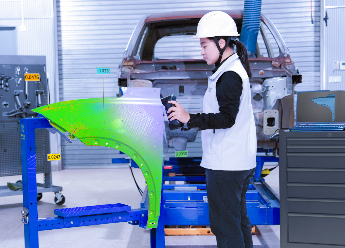
Scan-to-report: acquisition, alignment, CAD comparison, and reporting inside one digital loop.
Where It Pays Off: Documented QC Scenarios
Aircraft PMA components — Thailand
A manufacturer specializing in the design, certification, and production of key aircraft components replaced CMM-based checking of PMA components with a FreeScan Combo+ handheld 3D scanner. Setup changed first: for the same part, a CMM would take 2–3 days to program before data collection started, while the scanner required only connecting the power supply to the computer, with data captured in less than half a day. Fixtures disappeared too — CMM inspection can require multiple fixtures that take up to three days to design and manufacture, while the operator simply changes the scanner angle or flips the part. The team also noted the scanner is lightweight, portable, and easy to operate even for staff without specialist 3D scanning skills, with one employee estimating roughly half a day to become familiar with it. The system has been in use for more than two years.
EMI filter prototypes — Hungary
An electromagnetic interference (EMI) filter development and manufacturing factory adopted a FreeScan Combo handheld 3D laser scanner together with Geomagic Control X QC software to inspect and measure prototypes. The required measurements became feasible, with measurement time reduced from approximately two weeks with outsourced partners, or 3–4 days in the internal measurement lab, to an average of 2–3 hours. The scanner captures complete surface data, so future checks remain possible even when physical prototypes are unavailable — a capability the company has already used for product refinements.
Sheet metal stamping — China
An automotive stamping parts manufacturer inspects stamping parts immediately after production with a FreeScan Trak Nova wireless dynamic tracking and scanning system, without waiting for fixtures. Replacing part-specific fixtures with a general-purpose 3D scanning system eliminated a 1.5 to 2 month fixture development cycle per part, cutting project time by at least one third and removing the cost of custom tooling that ran to thousands of dollars per part. Non-contact measurement also removed the deformation risk that contact gauges pose to thin stamping parts.
High-precision moulds and customized industrial equipment — Thailand
An industrial machinery manufacturer uses a FreeScan Trak ProW+ system for high-precision mould and customized equipment inspection. Marker-free scanning removed preparation time, wireless operation improved flexibility on the shop floor, and inspection time per part dropped from 30–45 minutes to 10–15 minutes, with overall 3D inspection efficiency improving by approximately 60%. The higher-resolution scan data integrates with CAD/CAM workflows for reverse engineering, quality inspection, and design validation.
Large fabricated structures and refurbishment — Australia
A steel manufacturing company used a FreeScan Trak Nova system to assess and refurbish a 15-ton trommel screen shell returned from mineral processing plants. The scanner captured the flange bolt pattern and critical interfaces in detail, and the resulting scan data was compared directly against the original CAD model so engineers could identify deviations outside manufacturing tolerance and determine exactly where rectification was required. Inspection tasks that previously took days now take hours.
The same logic applies at the small end. In consumer electronics, high-precision 3D measurement of housings and components supports CAD comparison, dimensional deviation analysis, surface flatness inspection, deformation and warpage analysis, and R-angle and cross-section measurement — checks that are largely invisible to contact hand tools.
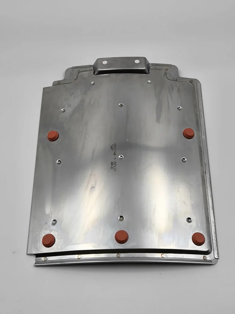
Aerospace PMA components: fixture-free, non-contact inspection replaced a 2–3 day CMM programming cycle.
Comparison Table: Measurement Options and Scanner Fit
The table below summarizes where each measurement approach is strongest. It draws on published measurement guidance and on the acceptance-test specifications of the scanner families described above, and it deliberately avoids claims that cannot be verified.
| Measurement approach | What it answers well | Where it breaks down |
|---|---|---|
| Hand tools (calipers, gauges) | Highly efficient for quickly checking basic dimensions and simple geometries, such as the diameter of a tube. | Limited to two-point features; cannot capture the complete 3D profile of complex curvatures or freeform surfaces; contact risks deformation on thin parts. |
| Coordinate Measuring Machine (CMM) | Widely recognized gold standard for absolute measurement accuracy; ideal for critical geometric features in highly regulated, stationary inspection workflows. | Tied to an environment-controlled lab; difficult to apply to massive castings or large-scale components; part programming and fixturing add setup time before measurement begins. |
| Consumer or hobbyist 3D scanner | Cost-effective for visual 3D digitization, basic design assistance, and digital asset creation. | Data lacks strict metrological traceability and cannot be used to sign off engineering quality reports. |
| Metrology-grade 3D scanner | Non-contact, full-field capture with lab-level accuracy on the factory floor: millions of points in seconds and instant color maps for deviation analysis. | On highly reflective, glossy, or translucent surfaces, an ultra-thin layer of scanning spray may still be required on some systems. |
Matching the scanner to the QC task is the second decision. All figures below come from the published acceptance-test specifications of each system, tested in an ISO/IEC 17025 accredited laboratory.
| System | Accuracy | Form factor and light source | QC tasks it fits |
|---|---|---|---|
| FreeScan Combo+ Wireless / FreeScan Combo Wireless | 0.02 mm | Wireless handheld, blue laser + infrared VCSEL, 550 g, Wi-Fi 7 | Shop-floor inspection of small to large parts, dark and reflective surfaces, marker-free scanning of large components |
| FreeScan Omni / FreeScan Omni Lite | 0.02 mm | Standalone wireless handheld, blue laser + IR VCSEL, 1.1 kg or less, on-device touchscreen | On-site scan-to-inspect and reporting without a laptop, first article inspection |
| FreeScan Trak Nova Series | 0.02 mm | Wireless dynamic tracking, marker-free, FOV up to 2600 × 2200 mm | Large parts and assemblies, large-scale dimensional inspection, automotive and marine MRO |
| FreeScan Trak ProW+ | 0.023 mm | Wireless dynamic tracking, 8.6 m tracking distance, 156 m³ single-station volume | Large-scale objects where marker application is impractical, casting and engineering machinery |
| OptimScan Q12/Q9 HD | 0.004 mm (small range), 0.01 mm (large range) | Fixed blue LED, four high-resolution cameras, 3.6 kg | Small precision parts, fine details and sharp edges, GD&T inspection, mold and tooling inspection |
| AutoScan Inspec2 | 10 microns | Desktop, three-axis automated, blue LED, 5 kg | Batch inspection of small identical parts, electronic components, small mechanical parts |
FAQ
Are metrology 3D scanner measurements traceable to international standards?
Yes. SHINING 3D scanners are calibrated using certified artifacts or calibration panels traceable to metrology standards, and inspection reports and calibration certificates traceable to VDI/VDE 2634 and ISO 10360 can be issued, subject to the actual certificates issued. The SHINING 3D Accuracy Laboratory is accredited to ISO/IEC 17025 by CNAS, and because CNAS is a signatory to mutual recognition arrangements such as the ILAC MRA, its reports and certificates are recognized internationally. The lab is certified for VDI/VDE 2634 Part 2 and Part 3 testing, and its systems align with ISO 10360-12 and ISO 10360-13 acceptance and reverification protocols.
Can a metrology 3D scanner replace calipers at every QC step?
No, and it should not. Hand tools are highly efficient for quickly checking basic dimensions — for example the diameter of a tube — and they remain the fastest answer for simple geometries. A metrology 3D scanner earns its place where the requirement is the 3D profile of complex curvatures, freeform surfaces, warpage, R-angle, or cross-section geometry, and where the result must be traceable in an inspection report. A realistic workflow combines both: calipers for simple dimensional checks, and 3D scanning for full-field inspection, first article inspection, and reverse engineering.
What drives the cost of switching from caliper checks to 3D scanning?
The main costs are the scanner configuration, inspection software, and operator training; the savings most often come from the tooling side. In one stamping project, dedicated fixtures took 1.5 to 2 months to design and build per part and cost thousands of dollars each, with complex parts potentially requiring two fixtures, while a general-purpose 3D scanning system handled any shape. Software licensing deserves attention: FreeScan Software and OptimScan Software are included without subscription fees. As a general benchmark, industrial inspection budgets for this class of equipment typically start from twenty thousand dollars.
Can we validate a scanner on our own parts before committing?
Yes. The recommended gate is to scan the parts that actually cause trouble — thin stamping parts, dark or reflective machined surfaces, or large fabrications — and compare the results with an existing reference measurement. Material adaptability, marker-free capability, and battery runtime are best judged on your own parts and your own shop floor rather than on a specification sheet. Calibration is worth planning as part of the routine: it is recommended for first use or after one to two weeks of inactivity, after severe vibration such as transport, if accuracy drops and alignment errors or unrecognized markers become frequent, or if scan data becomes incomplete or quality deteriorates noticeably.
How long does deployment take, and what support is included?
Standard lead time is 30 to 45 days, the minimum order quantity is one unit, every unit is 100% tested before shipping, and both remote and onsite support are available, along with logo and automation solution customization. To start a concrete evaluation, send the part type, critical tolerances, and expected inspection volume to campaign@shining3d.com, or download the catalogue at the link below.
Conclusion: Measure the Part, Not the Points
Calipers do not slow down QC because they are inaccurate — they slow it down because they answer too few questions per measurement. As tolerance bands tighten toward 0.025 mm in battery and structural applications, and as supplier audits increasingly expect traceable optical data, the cost of a key-point-only quality record keeps rising. A metrology 3D scanner changes the unit of work: one capture replaces a sequence of contact checks, the result is a full-surface digital record of the part, and the same dataset serves inspection, reverse engineering, and future re-checks. The documented results — 30–45 minutes down to 10–15 minutes per part, 3–4 days down to 2–3 hours for prototype measurement, and inspection tasks that moved from days to hours — come from the workflow change, not from measuring faster with the same tool.
SHINING 3D (Shining 3D Tech Co., Ltd.) was established in 2004 and specializes in the field of high-precision 3D vision technology, developing the software and hardware behind its metrology 3D scanners, professional 3D scanners, entry-level 3D scanners, and dental 3D solutions. The company is headquartered in Hangzhou, China, with subsidiaries in Stuttgart, Barcelona, California, Florida, and Tokyo. Learn more at www.shining3d.com.
Next step
Send us the part, the tolerance, and the current inspection time per unit. We will recommend the metrology 3D scanner configuration that fits the workflow — handheld, standalone, dynamic tracking, fixed, or automated desktop — and confirm sample evaluation and lead time.
Email: campaign@shining3d.com · Sales and support: marketing@shining3d.com · Tel: +86 571 8299 9050
Download the product catalogue: SHINING 3D 3D Digitizing Introduction (PDF)

Talk to the SHINING 3D team about validating a metrology 3D scanner on your own parts.
Have Questions or Need More Details?
Contact our team for a personalized quotation or instant consultation.
Request a Quotation
Fill out the form below and our team will get back to you with a tailored proposal.
WhatsApp Direct Chat
Prefer to chat in real-time? Message us on WhatsApp for instant assistance & quick answers.
- Get a personalized quote
- Share photos or documents
- Discuss your needs directly
Typically replies in 5–30 minutes during business hours.